Because of the holidays, TI E2E™ design support forum responses will be delayed from Dec. 25 through Jan. 2. Thank you for your patience.

EVM430-FR6043: How to work in pulse echo mode?

Part Number: EVM430-FR6043

Tool/software:

Hi everyone,

I am using the demo code "FR6043_USSSWLib_template_example" for my gas meter setup. In addition I use the Ultrasonic Sensing Design Center to configure my setup properly. When I use both transducers, everything works fine. 

To use the Board in pulse echo mode I already tried connecting one transducer to both jumpers. The captured ADC signal was not satisfactory because the transmitted pulse is probably received immediately and superimposed on the reflected signal. The reflected signal needs approximately 110 µs. The ADC capture is shown below. The reflected signal is weak, but a new gas meter setup for pulse echo mode is in development.
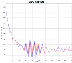
I alredy tried different capture sequences when both transducers are connected, but I never received a time of flight of 110 µs. In this context I do not really understand what the capture sequence of CH0_CH1 means. Does it mean, that it excites in CH0 and receives in CH0, then it excites in CH1 and receives in CH0? But according to the schematic of the EVM430-FR6043 the CH1 is not used to excite or receive any transducer signal. Have I misunderstood something here?

So, are there any other possibilities to modify the template to send and receive using only one transducer?

Thank you, Sincerely

Leon

  • Hi Leon,

    Have you checked with this app note before. https://www.ti.com/lit/an/slaa951a/slaa951a.pdf

    It uses single transducer for the level sensing application. It may help on your design.   

    Best regards,

    Cash Hao

  • Hi Cash,

    Thank you for your response. With the new meter setup the signal looks much better, but there is still the problem, that the transmitted pulse is superimposed on the reflected signal when connecting one transducer to both jumpers, as it is described in the app note you sent. The higher the reflection distance, the better the signals are separated from each other. Unfortunately, we want to keep the measuring distance as small as possible, i.e. increasing the measuring distance until the signal quality is satisfactory is not a solution. 

    So I think you have to change the template somehow so that this overlay of these signals does not happen. Or is there any other possibility?

    Best regards,

    Leon

  • Hi,

    So, the reflecting issue is basically causing by hardware side. And I do not think we can solve it on the software side. I do not have more ideas on how to solve this now. 

    Best regards,

    Cash Hao

  • Hi Cash,

    I have another question. I was wondering why the transmitted pulse is that long. The ADC capture in my original question above has a gap between pulse start of 90 µs and a capture duration of 100 µs. So a time of 115 µs passes till the ADC signal is detected. Since you can still see the transmitted pulse on the left side of the ADC signal, it takes the same time to decay. But the number of pulses is only 6 and I have a 500 kHz transducer. So the transmitted pulse should take approximately 10 µs. Why does the pulse take that long to decay? Are there any input capacitances to consider in the circuit?

    Best regards,

    Leon

  • Hi,

    Sorry for the late response. Just get back from paternity leave.

    The pulses should not take that long(90us) to decay. Do you have a screen shot of the ADC data with the long decay? We can check on it first.

    Best regards,

    Cash Hao

**Attention** This is a public forum