This thread has been locked.

If you have a related question, please click the "Ask a related question" button in the top right corner. The newly created question will be automatically linked to this question.

MSP430F2617: Issues with DCO Frequency

Part Number: MSP430F2617

Tool/software:

Hi all,

I apologize if this has been covered in a different question, please link it if so. I have searched to the best of my ability and cannot come up with an answer that seems to work.

Problem: Setting DCOCLK to anything other than 1MHz has proved to be impossible and I cannot figure out why.

Attempted implementation: 

    DCOCTL = 0;                               // Select lowest DCOx and MODx settings
    BCSCTL2 = 0;
    BCSCTL1 = CALBC1_8MHZ;
    DCOCTL = CALDCO_8MHZ;                     // Load 8MHz constants


For my project, I would like to use 8MHz DCO since I would like to use PWM frequencies up to 100KHz for my application.

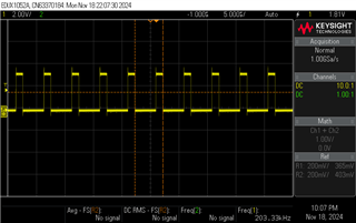
It seems as though the above is not working as intended. When using a Timer with CCR0 set to 100, I get a frequency of 200kHz, which makes no sense. See below: 

I've found some information via this forum that has alluded me to the fact that InfoA is getting erased when I do a flash via BSL (BSLDEMO.exe). I could not sort out how to fix that, so I went back to using CCS and JTAG programming. 

I started off by flashing MSP430x261x_dco_flashcal.c which is found under the examples (I just searched "DCO) to reinstate the correct values that should exist in InfoA that "msp430f2617.h" references. Maybe I am understanding incorrectly but I believe that the header file pulls the information for macros such as "CALDCO_8MHZ" and "CALBC1_8MHZ" from InfoA. After reflashing my own project following the "dco_flashcal", it seems as though my issue has not been solved and I still get a 200kHz PWM frequency after using the code above.

Via another thread, I found that setting DCOTL and BCSCTL1 to 0x8d seems to get the values accurate to what they should be, if the data in InfoA was correct. I tried this and it seemed to actually work, but I do not quite understand why it does not work by default using the header file as intended.

The problem, to me, seems like the DCOCTL and/or BCSCTL1 is not being properly configured.

Does anyone have any insight into this? I'm not sure I should be manually setting these values as opposed to using the correct values intended by the header file / InfoA. 

Thanks for your time.

  • 1) Before using the calibration data I always validate the checksum. If that fails, you can either fall back to uncalibrated settings or halt if that will not work for you.

    2) Did you ever examine what is in infoA?

    3) When running the flashcal.c code did you have a 32kHz crystal connected for it to use as a reference?

  • Which checksum would I be validating here? Don't I need calibrated settings? 

    I don't know that I can examine what is in InfoA, but what I can say is that BSL is not accepting the "default" RX password so I cannot read from it using BSLDEMO. Despite not knowing what it is in InfoA, I can safely assume that the data in CALDCO_8MHZ and CALBC1_8MHZ are not correct since my clocks are all wrong. When I remove the lines changing the clock speed, I notice that the default 1MHz seems to work fine.

    Ah, perhaps that is why flashing with flashcal.c did not fix anything. I do not have a 32kHz crystal on my board. I thought that was only for ACLK.

  • Which checksum would I be validating here? Don't I need calibrated settings? 

    Read chapter 24 of the guide on the TLV structure.

    Only you can decide if you need the calibrated settings.

  • The main goal is to obtain 8MHz DCOCLK, does not really matter which why I go about it. This just seems like unwanted behavior when using <msp430f2617.h>. Am I correct in that assumption?

  • The F2-series BSL makes it very easy to accidentally erase the clock-calibration constants (infoA). Best is to avoid it.

    Use the CCS debugger (Memory Browser maybe) to examine locations 0x10F8-FF. If they're =0xFF, they've been erased. It's also possible they contain constants computed using the VLO (vaguely resembles 10kHz) as a reference, which as you observe aren't very useful.

    As published, dco_flashcal assumes a 32kHz crystal. With a small hack (LFXT1S=3) you should be able to feed a 32kHz clock into XIN. Such a clock could come from a signal generator or another MCU if you have one on your bench.

  • Is that an indirect way of saying not to use BSL with this chipset? That's a shame, I was just trying to make it easier for my colleagues / take up less resources (space) on my board if I could get away with just a single USB interface. Seems as though specifically BSL 2.13 is what causes infoA to be easily erased?

    I will try the suggestion to view what's actually inside of infoA at the moment and give the workaround a try to attempt a reflash of infoA. Will be back with an update.

  • It started with BSL 2.01 [Ref BSL UG (SLAU319AE) Sec 2.4.4.4 ("Note")], and has to do with it clearing LOCKA (unlocking InfoA) automatically. After that any Mass Erase (intentional or accidental) will erase InfoA. In the BSL, almost any mistake will result in a Mass Erase, and it only takes one.

**Attention** This is a public forum