This thread has been locked.

If you have a related question, please click the "Ask a related question" button in the top right corner. The newly created question will be automatically linked to this question.

ez430 Application UART is NOT compatible with Launchpad Application UART


MSP430 Team-

I've come across a major tools incompatibility problem while trying to use the Application UART on the MSP430 Launchpad.

The serial RX/TX lines are swapped between the two tools.

This is taken from Figure 6 of the MSP-EXP430G2 User's manual:

Notice that BTXD ends up getting routed to P1.2, and then to pin 6 of SL127L6TH, the pin adjacent to the ground pin (5).

From Fig.4  of the User's Manual of the ez430-RF2500 tool, notice that RX data is present on the pin adjacent to GND:

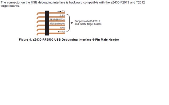
It is therefore IMPOSSIBLE for this combination to work, and I have observed the incompatiblity on my bench:

  • HI Antennahead,

    thank you for the finding! We are fully aware of this behavior. It was actually a conscious decision during the development the board. Since the LaunchPad emulator, the 6-pin eZ430 header, and the G2xxx device all share the TX/RX pins for communications, we could only support two UART paths between the three sources. Since the application focus is placed on the G2xxx device itself, it was decided to support UART communications for the G2xxx device, both to the emulator and the 6-pin header. This of course came with a sacrifice of the back-channel UART for the 6-pin eZ430 header.

    Hope this addresses your concern.

    Regards,

    Dung

  • Dung-

    The documentation for the MSP-EXP430G2, Figure 4 (see my original post) shows that RF2500T target board, ala ez430-RF2500 kit, attached to the Launchpad.

    If I understand what you're saying, the idea would then be only for the RF2500T to interface to the G2xxxx device on the Launchpad, rather than the USB serial port on the debugger side.  In other words, the RF2500T can't use the back channel UART to the PC.

    I was trying to use the Launchpad and back-channel UART on a project that was designed around the documentation for the ez430 6 pin interface.

    This is extremely confusing.  I guess I just need to stick to using the ez430 debugger for my projects using the back channel UART to the PC.

    Best, Steve


  • UART communication is a single peer-to-peer connection. Not a bus.
    However, the wiring on the board is a triangle connection, which is impossible with the UART.

    Of the three peers, one of them can talk to one or the other of the othe rtwo, bot the other two cannot talk to each other. And only one connection can be active at a time too.

    To the question was: whcih one of the three shall be the one that can talk with both others. And the winner was the G chip, as this is the main focus of the board. The G chip can either talk to the USB side or to the RF, but the RF talk to the USB.

    The alternatives would have been that both, the G and the RF can talk to USB (but only one of them at the same time) buit they cannot talk to each other (which makes data excange impossible), or the RF can talk to the G chip and the USB but the G cannot talk to USB., Which is even less desireable.

    The only solution would have been a jumper field on the RF connector, so you can wire the connection this or that way. Well,t eh RF is meant as extension module for G experiemnts, and not the G board as base station for the RF module, so the decision was clear.

  • Hi Steve,

    Antennahead said:

    The documentation for the MSP-EXP430G2, Figure 4 (see my original post) shows that

    RF2500T target board, ala ez430-RF2500 kit, attached to the Launchpad. 

     We still include this picture because it is still possible to program your RF2500T off of that 6-pin ez430 interface on the Launchpad, which is what that section of the user's guide discusses. The only issue is with the backchannel UART communicating to the PC due to there being 3 endpoints then for the communication, as Jens-Michael and Dung mentioned, so a choice had to be made on which devices should be able to communicate.

    The function of the UART with the eZ430-RF2500 is explained below that picture in section 4.4 of the User's guide as well:

    The application UART, on the other hand, is connected directly to the LaunchPad target device,

    and jumper J3 can be closed to monitor the transmission from the LaunchPad target to the

    attached eZ430. This way both possible connections, from the device to the PC and from the

    device to the eZ430, can be established without changing the direction of the UART pins.

    So these pins are flipped so that in an application you can communicate between the target G2xx device and the eZ430-RF2500, or between the target G2xx device and the PC, just not between the PC and the eZ430 RF2500 - we couldn't have it all three ways, and since this board is primarily intended as a tool for the G2xx value line parts, we focused our connectivity around the G2xx.

    Regards,

    Katie


**Attention** This is a public forum