This thread has been locked.

If you have a related question, please click the "Ask a related question" button in the top right corner. The newly created question will be automatically linked to this question.

MSP430FR4131: weird FRAM usage

Part Number: MSP430FR4131

Tool/software:

Hello.

I am using CCS V12.6.0.00008 & msp430fr4131. I have a weird FRAM usage in this code:

//  Built with Code Composer Studio v12
//******************************************************************************
#include <msp430fr4131.h>

#define us      16          // define the the value of uSec to be used in delay & _delay_cycles functions
#define ms      16000       // define the the value of mSec to be used in delay & _delay_cycles functions
#define _5ms    80000       // define the the value of 5mSec to be used in delay & _delay_cycles functions
#define _10ms   160000      // define the the value of 10mSec to be used in delay & _delay_cycles functions
#define _50ms   800000      // define the the value of 50mSec to be used in delay & _delay_cycles functions
#define _100ms  1600000     // define the the value of 100mSec to be used in delay & _delay_cycles functions
#define _sec    16000000    // define the the value of Sec to be used in delay & _delay_cycles functions

//******************************************************************************
void initGPIO()
    {
    // make all inputs
    P1DIR = 0x00; P2DIR = 0x00; P3DIR = 0x00; P4DIR = 0x00;
    P5DIR = 0x00; P6DIR = 0x00; P7DIR = 0x00; P8DIR = 0x00;
    // Enable Pull up/down R
    P1REN = 0xFF; P2REN = 0xFF; P3REN = 0xFF; P4REN = 0xFF;
    P5REN = 0xFF; P6REN = 0xFF; P7REN = 0xFF; P8REN = 0xFF;
    // Make all inputs pulled up
    P1OUT = 0xFF; P2OUT = 0xFF; P3OUT = 0xFF; P4OUT = 0xFF;
    P5OUT = 0xFF; P6OUT = 0xFF; P7OUT = 0xFF; P8OUT = 0xFF;

    // Disable the GPIO power-on default high-impedance mode
    // to activate previously configured port settings
    PM5CTL0 &= ~LOCKLPM5;
    }
//******************************************************************************
void initClock()
    {

    // Configure one FRAM wait state as required by the device data sheet for MCLK
    // operation beyond 8MHz _before_ configuring the clock system.
    FRCTL0 = FRCTLPW | NWAITS_1;

    __bis_SR_register(SCG0);    // disable FLL
    CSCTL3 |= SELREF__REFOCLK;  // Set REFO as FLL reference source
    CSCTL0 = 0;                 // clear DCO and MOD registers
    CSCTL1 &= ~(DCORSEL_7);     // Clear DCO frequency select bits first
    CSCTL1 |= DCORSEL_5;        // Set DCO = 16MHz
    CSCTL2 = FLLD_0 + 487;      // set to fDCOCLKDIV = (FLLN + 1)*(fFLLREFCLK/n)
                                //                   = (487 + 1)*(32.768 kHz/1)
                                //                   = ~16 MHz (= 15990784 Hz)
    __delay_cycles(3);
    __bic_SR_register(SCG0);                        // enable FLL
    while(CSCTL7 & (FLLUNLOCK0 | FLLUNLOCK1));      // FLL locked

    CSCTL4 = SELMS__DCOCLKDIV | SELA__REFOCLK;

    }


//********************************************************
// main program variables
//********************************************************


char batt_body1 = 0;      //  will represent the outer body
char batt_body2 = 0;      //  will represent the outer body
char batt_body3 = 0;      //  will represent the outer body
char batt_body4 = 0;      //  will represent the outer body

char batt_top1 = 0;      //  will represent the top part
char batt_top2 = 0;      //  will represent the top part
char batt_top3 = 0;      //  will represent the top part
char batt_top4 = 0;      //  will represent the top part


void main( void )
{
    WDTCTL = WDTPW | WDTHOLD;   // Stop watch dog timer
    initGPIO();                 // setup digital IO pins
    initClock();                // setup Clock = 16MHz

    _delay_cycles(_sec);        // delay 1


    batt_body1 = 1;
    batt_body2 = 1;
    batt_body3 = 1;
    batt_body4 = 1;

    batt_top1 = 1;
    batt_top2 = 1;
    batt_top3 = 1;
    batt_top4 = 1;


    while (1)
        {
        _delay_cycles(_sec);    // delay 2
        }//END OF while (1)
}// END OF MAIN

That code as is, will give an FRAM usage of 798 out of 3968 20%.

If "delay 1" line is removed, it will give an FRAM usage of 776 out of 3968 19%.

But if "delay 2" line is remove (keeping "delay 1"), it will give an FRAM usage of 242 out of 3968 6%.

What also make it even more, if I keep both delays and remove all the eight batt_XXX variables assigning, it will give an FRAM usage of 264 out of 3968 6%.

So what is happening.

Thanks

  • Hi Sami,

    I'm not sure why removing delay2 and keeping delay1 makes a difference in code size.  It shouldn't, since there is another  "__delay_cycles(3)" as part of the clock init.  The compiler has already linked in that function.  Adding additional calls to func __delay_cycles() should only add a few bytes for handling the stack entry and exit.

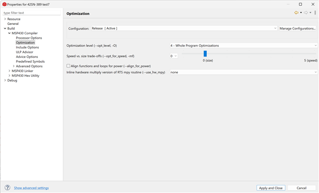
    What compiler optimization settings are you using?

    Now for the variables, if you start with an empty project and add only one variable and both declare and define it outside of main, the linker will include runtime initialization code for those variables prior to the start of main, but which makes the code size large, (looks like ~500 or so bytes in this case ).  

    #include <msp430.h> 
    
    #define RUNTIME_INIT
    
    #ifdef RUNTIME_INIT
        /* Declare only */
        char peach = 0;
    #else
        char peach;
    #endif
    
    /**
     * main.c
     */
    int main(void)
    {
    
    	WDTCTL = WDTPW | WDTHOLD;	// stop watchdog timer
    
    	/* Comment out variable peach and code size is 48 bytes */
    	peach = 1;
    	return 0;
    }

    If you only declare the variable outside of main, but then define it in main (assign a value to it), as shown below, the size is only 230 bytes.  The runtime initialization before main is not needed as the variable is assigned a value in main. 

    #include <msp430.h> 
    
    //#define RUNTIME_INIT
    
    #ifdef RUNTIME_INIT
        /* Declare only */
        char peach = 0;
    #else
        char peach;
    #endif
    
    /**
     * main.c
     */
    int main(void)
    {
    
    	WDTCTL = WDTPW | WDTHOLD;	// stop watchdog timer
    
    	/* Comment out variable peach and code size is 48 bytes */
    	peach = 1;
    	return 0;
    }

    And of course if you declare or define and don't use the variable at all, the compile is smart enough not to include nor add the associated runtime initialization code, resulting in a code size of only 48 bytes.

    #include <msp430.h> 
    
    //#define RUNTIME_INIT
    
    #ifdef RUNTIME_INIT
        /* Declare only */
        char peach = 0;
    #else
        char peach;
    #endif
    
    /**
     * main.c
     */
    int main(void)
    {
    
    	WDTCTL = WDTPW | WDTHOLD;	// stop watchdog timer
    
    	/* Comment out variable peach and code size is 48 bytes */
    	//peach = 1;
    	return 0;
    }

  • //  Built with Code Composer Studio v12
    //******************************************************************************
    #include <msp430fr4131.h>
    
    #define us      16          // define the the value of uSec to be used in delay & _delay_cycles functions
    #define ms      16000       // define the the value of mSec to be used in delay & _delay_cycles functions
    #define _5ms    80000       // define the the value of 5mSec to be used in delay & _delay_cycles functions
    #define _10ms   160000      // define the the value of 10mSec to be used in delay & _delay_cycles functions
    #define _50ms   800000      // define the the value of 50mSec to be used in delay & _delay_cycles functions
    #define _100ms  1600000     // define the the value of 100mSec to be used in delay & _delay_cycles functions
    #define _sec    16000000    // define the the value of Sec to be used in delay & _delay_cycles functions
    
    //******************************************************************************
    void initGPIO()
        {
        // make all inputs
        P1DIR = 0x00; P2DIR = 0x00; P3DIR = 0x00; P4DIR = 0x00;
        P5DIR = 0x00; P6DIR = 0x00; P7DIR = 0x00; P8DIR = 0x00;
        // Enable Pull up/down R
        P1REN = 0xFF; P2REN = 0xFF; P3REN = 0xFF; P4REN = 0xFF;
        P5REN = 0xFF; P6REN = 0xFF; P7REN = 0xFF; P8REN = 0xFF;
        // Make all inputs pulled up
        P1OUT = 0xFF; P2OUT = 0xFF; P3OUT = 0xFF; P4OUT = 0xFF;
        P5OUT = 0xFF; P6OUT = 0xFF; P7OUT = 0xFF; P8OUT = 0xFF;
    
        // Disable the GPIO power-on default high-impedance mode
        // to activate previously configured port settings
        PM5CTL0 &= ~LOCKLPM5;
        }
    //******************************************************************************
    void initClock()
        {
    
        // Configure one FRAM wait state as required by the device data sheet for MCLK
        // operation beyond 8MHz _before_ configuring the clock system.
        FRCTL0 = FRCTLPW | NWAITS_1;
    
        __bis_SR_register(SCG0);    // disable FLL
        CSCTL3 |= SELREF__REFOCLK;  // Set REFO as FLL reference source
        CSCTL0 = 0;                 // clear DCO and MOD registers
        CSCTL1 &= ~(DCORSEL_7);     // Clear DCO frequency select bits first
        CSCTL1 |= DCORSEL_5;        // Set DCO = 16MHz
        CSCTL2 = FLLD_0 + 487;      // set to fDCOCLKDIV = (FLLN + 1)*(fFLLREFCLK/n)
                                    //                   = (487 + 1)*(32.768 kHz/1)
                                    //                   = ~16 MHz (= 15990784 Hz)
        __delay_cycles(3);
        __bic_SR_register(SCG0);                        // enable FLL
        while(CSCTL7 & (FLLUNLOCK0 | FLLUNLOCK1));      // FLL locked
    
        CSCTL4 = SELMS__DCOCLKDIV | SELA__REFOCLK;
    
        }
    
    
    //********************************************************
    // main program variables
    //********************************************************
    
    
    char batt_body1;      //  will represent the outer body
    char batt_body2;      //  will represent the outer body
    char batt_body3;      //  will represent the outer body
    char batt_body4;      //  will represent the outer body
    
    char batt_top1;      //  will represent the top part
    char batt_top2;      //  will represent the top part
    char batt_top3;      //  will represent the top part
    char batt_top4;      //  will represent the top part
    
    
    void main( void )
    {
        WDTCTL = WDTPW | WDTHOLD;   // Stop watch dog timer
        initGPIO();                 // setup digital IO pins
        initClock();                // setup Clock = 16MHz
    
        _delay_cycles(_sec);        // delay 1
    
    
        batt_body1 = 1;
        batt_body2 = 1;
        batt_body3 = 1;
        batt_body4 = 1;
    
        batt_top1 = 1;
        batt_top2 = 1;
        batt_top3 = 1;
        batt_top4 = 1;
    
    
        while (1)
            {
            _delay_cycles(_sec);    // delay 2
            }//END OF while (1)
    }// END OF MAIN
    

    Thank you Dennis for the declaring tip. I used to work with Microchip PIC and that wasn't an issue.

    Here is a screen shot of my compiler optimization settings:

    I did a test on my code in the 1st post with only declaring the variables.  

    I got, FRAM usage of 480 out of 3968 12%.

    removing delay 1 & keep delay 2, FRAM usage of 458 out of 3968 11%.

    removing delay 2 & keep delay 1, FRAM usage of 230 out of 3968 5%.

    still a big difference. 

  • Adding additional calls to func __delay_cycles() should only add a few bytes for handling the stack entry and exit.

    This isn't a function call. The compiler generates code on the fly that consumes the desired number of cycles. For example:

      __delay_cycles(16000000);
        c030:       1e 14           pushm.a #2,     r14     ;20-bit words
        c032:       3d 40 fc 48     mov     #18684, r13     ;#0x48fc
        c036:       3e 40 3c 00     mov     #60,    r14     ;#0x003c
    
    0000c03a <.L1^B1>:
        c03a:       1d 83           dec     r13             ;
        c03c:       0e 73           sbc     r14             ;
        c03e:       fd 23           jnz     $-4             ;abs 0xc03a
        c040:       0d 93           cmp     #0,     r13     ;r3 As==00
        c042:       fb 23           jnz     $-8             ;abs 0xc03a
        c044:       1d 16           popm.a  #2,     r14     ;20-bit words


  • David, 

    doesn't that mean I should see the same amount of memory saving in both cases.

    What is special about using __delay_cycles() in and out the while(1) loop?

    As I understand, both will be fond one time in the assembly code. Identical copy.

  • Examine the assembly code produced to see what is going on.

**Attention** This is a public forum