This thread has been locked.

If you have a related question, please click the "Ask a related question" button in the top right corner. The newly created question will be automatically linked to this question.

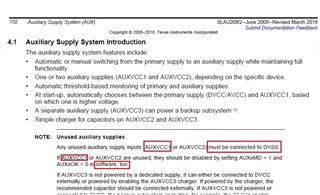
MSP430F6779A: an AUX1MD be configured to be hardware controlled (AUX1MD = 0) in case AUXVCC1 is connected to DVSS (unused)?

Part Number: MSP430F6779A

Tool/software:

Hi,

I would like to consult about AUXxMD configuration since our project has 2 different types of boards below:

Board #1: Connect DVCC pin to DC power supply (3.3 V), Connect AUXVCC1 pin to battery (3.3 V)

Board #2: Connect DVCC pin to DC power supply (3.3 V), Connect AUXVCC1 pin to DVSS (unused)

Since I need common firmware for 2 different types of boards

So can AUX1MD be configured to be hardware controlled (AUX1MD = 0) in case AUXVCC1 is connected to DVSS (unused)?

(note; i have known that in the user guide recommend setting AUX1MD = 1 and AUX1OK = 0)
  • Hi, 

    So can AUX1MD be configured to be hardware controlled (AUX1MD = 0) in case AUXVCC1 is connected to DVSS (unused)?

    Why not try to use a GPIO to read hardware voltage level that indicates whether the device has a backup power supply or a single power supply.

    Regards,

    Helic

  • Hi,

    I think in our present code already work.
    by checking AUXVCC1 by the AUX module.

        // Clear the LOCKAUX bit, enable the write access to the AUXCTLx registers
        AUXCTL0 = AUXKEY;
        AUXIE     = 0x0000;                         // AUXIE
        AUXCTL2   =  (AUXMR_0 | AUX0LVL_6 | AUX1LVL_5 | AUX2LVL_0);
                                                    // AUXCTL2 �? Auxiliary supply monitoring rate: 0.
                                                    //            AUX0LVL : 3.0V.
                                                    //            AUX1LVL : 2.7V.
                                                    //            AUX2LVL : 0.0V.
    
        AUXCTL1 |=   AUX2MD;                        // AUXCTL1    Software controlled AUXVCC2 auxiliary supply mode.
        AUXCTL1 &= ~(AUX0MD | AUX1MD);              //            Hardware controlled AUXVCC1 auxiliary supply mode.
                                                    //            Hardware controlled AUXVCC0 auxiliary supply mode.


    When Board #2 Connect AUXVCC1 pin to DVSS (unused).
    the AUXVCC1 voltage is 0 v. so the MCU will always switch to DVCC automatically. right?

  • Hi, 

    When Board #2 Connect AUXVCC1 pin to DVSS (unused).
    the AUXVCC1 voltage is 0 v. so the MCU will always switch to DVCC automatically. right?

    In TRM: 4.1 Auxiliary Supply System Introduction

    At start-up, automatically chooses between 
    the primary supply (DVCC/AVCC) and AUXVCC1, 
    based on which one is higher voltage.
    

    This will be handled by hardware.

    Regards,

    Helic

**Attention** This is a public forum