MSP430FR2355: Getting Source code for the PIR motion detection demo to work on Dev Board

Part Number: MSP430FR2355

Tool/software:

Hi, 

I was looking at the demo code provided in the forum  https://e2e.ti.com/support/microcontrollers/msp-low-power-microcontrollers-group/msp430/f/msp-low-power-microcontroller-forum/1041311/msp430fr2355-source-code-for-the-pir-motion-detection-demo and trying to get it running on a MSP430FR2355 Dev Board.

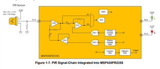
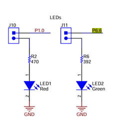
However, the code does not seem to reflect the pinout and SACs used in the article https://www.ti.com/lit/an/slaae30/slaae30.pdf?ts=1732770319246. Is this code suppose to work on the Dev Board? I changed the code so that it maps the LEDs to the correct pins on the dev board of P1.0 and P6.6 like in the article, but the red led seems to trigger periodically regardless of any motion on the pir sensor. Any suggestions on what I can change?

The only connections I have to the board is a pir sensor signal pin connected to the P1.3 pin with a 47K biasing resistor to GND. Power to the PIR sensor is 3.3V.

  • Hi Zoey,

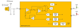
    The code provided is for the MSP430FR2355, but the TI reference hardware that you are referring to is not for the MSP430FR2355. I wanted to know if there was code that was run for the MSP430FR2355 LaunchPadTm development kit that supported this PIR detection demo. It seems that Figure 1.7 in the link that I provided does not reflect the provided code.

  • Hi Yixing,

    Sorry for the wrong link!

    The code is used for reference self hardware demo. Let me ask for our internal team if there is a code based on launchpad. But as far as I know, there wasn't.

    Regards,

    Zoey

  • Hi Zoey,

    Thanks! It be great to know what I could possibly modify in the code to get it to work on the launchpad.

  • Hi Yixing,

    I have not reviewed this code before.

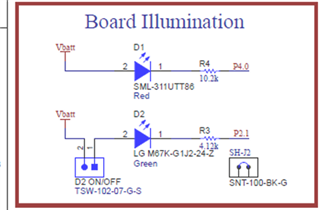
    But seen from the schematic, the LED is driven by P4.0 and P2.1 not P6.6 nor P1.0

    I think there are a bit difference between schematic(reference design provide) and block diagram.

    What's more, the LED driven is pull- down in launchpad and it is also differ from the reference design block diagram. I'm not sure if these differences will lead to the results you get now.

  • Oh I see, I'll take a look at that. Could you also help me ask the internal team on how they viewed and visualized the data logging in the code provided. It seemed that they used that code to generate the data for the graphs shown in the design reference file.

  • Hi Yixing,

    I will check with our internal team, but it will take maybe a long time as our U.S. team is in thanksgiving holiday.

    Regards,

    Zoey

  • Hi Yixing,

    I just get some response from my colleague:

    1.The code is corresponding to the App note But it is designed for customer board not on LaunchPad, and use MSPFR2353.

    2. If you change the LED pin to LaunchPad, it might be workable. But the hardware need to be double checked. 

    3.And the PIR signal is very sensitive. If the signal-to-noise ratio is too low, it will also lead to abnormal results. As my colleague said

    "Could be due to wiring/header connections.  Could be that he doesn't have a PIR lense.   Red LED in code detects motion.  If he is getting random red LEDs when nothing is moving, then the code is to sensative for the level of noise from his setup. He can work on making less noise.  He can also change the PIR Motion threshold in the code."

    4. As for datalogging, he said "what we would do is just run the PIR code via the debugger then pause it and "Read Memory" to dump the datalog buffers.  Then I'd copy and paste those into Excel. "

    Also I want to mention that we did port this design to M0 and add samll updates: https://www.ti.com/lit/an/slaaef6/slaaef6.pdf?ts=1733082851765.

    Regards,

    Zoey

  • Hi Zoey,

    The M0 looks interesting and I like that it has a demo on the launchpad for pir, but the main reason I was looking at the MSPFR2355 was because it included 4 SAC Opamps. I hoping to adapt this solution to monitor 2 PIR sensors where the first opamp in the chain would be fixed instead of programmable. It looks like the M0 only has 3 Opamps. Could you possibly point me towards a better chip solution if I was to work with 2 PIR sensors?

  • Hi Yixing,

    So 1 PIR will need 2 OPA, right? Sorry I am not familiar with PIR solution.

    If you want 2 PIR, I think MSPFR2355 could be a better option.

    But I will discuss with my colleague to see if there is any better solution.

    Regards,

    Zoey

**Attention** This is a public forum