Because of the holidays, TI E2E™ design support forum responses will be delayed from Dec. 25 through Jan. 2. Thank you for your patience.

MSP430FR2155: Using External 5MHz Oscillator On XT1

Part Number: MSP430FR2155
Other Parts Discussed in Thread: MSP430FR2355, LP-MSPM0G3507

Tool/software:

My Current Code to test setting up the oscillator is as follows:

int main(void) {
    WDT_A_hold(WDT_A_BASE);
//Configure MCLOCK OUtput Pin
    GPIO_setAsPeripheralModuleFunctionOutputPin(
                        GPIO_PORT_P3,
                        GPIO_PIN0,
                        GPIO_PRIMARY_MODULE_FUNCTION
                        );
//Configure XIN and XOUT pins
    GPIO_setAsPeripheralModuleFunctionInputPin(
               GPIO_PORT_P2,
               GPIO_PIN7,
               GPIO_SECONDARY_MODULE_FUNCTION
           );
//Turn on bypass mode
    CS_bypassXT1();
//source MCLOCK from XT1
    CS_initClockSignal(CS_MCLK,CS_XT1CLK_SELECT,CS_CLOCK_DIVIDER_1);
//Clear flags after starting oscillator
    CS_clearAllOscFlagsWithTimeout(1000);
    
    while(1){

    }
}

When run this code gets stuck trying to call CS_bypassXT1(). It gets stuck on the following while statement in cs.c:

while (HWREG8(CS_BASE + OFS_CSCTL7) & (XT1OFFG)) {
    //Clear OSC fault flags
    HWREG8(CS_BASE + OFS_CSCTL7) &= ~(XT1OFFG);

    // Clear the global fault flag. In case the XT1 caused the global fault
    // flag to get set this will clear the global error condition. If any
    // error condition persists, global flag will get again.
    HWREG8(SFR_BASE + OFS_SFRIFG1) &= ~OFIFG;
}

Any help would be appreciated

  • Have you try the register level code? Or could you share the whole project zip file here?

  • Clock Test.zip

    I've looked through the register level. It seems to get an oscillator fault flag, but I haven't been able to find a specific explanation as to what could cause that.

  • It seems like we are facing a very similar issue with the external clock connected to Xin, which causes the MSP to lock up. Initially, we thought the MSP was locking when clearing the global oscillator fault flag. However, after further investigation, we found that the MSP430FR2355 gets stuck when switching from the internal DCO (800kHz) to the external clock.

    The MCU can remain in this state for some time, and we observed that this behavior is temperature-dependent. After a while, the CPU starts working normally with the external clock. The external clock is not interrupted, and it does not appear to be the cause of the problem.

    Our post from last week: MSP430FR2355: MCU Lockup, Clock Issue?"

  • I think you may be right. By stuck do you mean endlessly looping your line:

    while (HWREG8(SFR_BASE + OFS_SFRIFG1) & OFIFG);

    I also have not been able to replicate your temperature issues. I temperature cycled it with a less elegant freeze spray and heat gun but it never escaped the loop.

  • Yes, we also first noticed the behavior using freeze spray and a heat gun. Then we placed the hardware into a temperature chamber.

    We also tried the following: you can enable MCLK output on a pin. In normal operation, you should first see the internal clock at around 800kHz, and then it should switch to the external clock. However, in our case, sometimes the switch happens, and sometimes it doesn’t.

    To test if our code gets stuck in the oscillator fault while loop:

        do
        {
            GPIO_setOutputLowOnPin(GPIO_PORT_P4, GPIO_PIN1);
            //Clear XT1 and DCO fault flags
            HWREG8(CS_BASE + OFS_CSCTL7) &= ~(XT1OFFG | DCOFFG);
    
            // Clear the global fault flag. In case the XT1 caused the global fault
            // flag to get set this will clear the global error condition. If any
            // error condition persists, global flag will get again.
            HWREG8(SFR_BASE + OFS_SFRIFG1) &= ~OFIFG;
            GPIO_setOutputHighOnPin(GPIO_PORT_P4, GPIO_PIN1);
        } while (HWREG8(SFR_BASE + OFS_SFRIFG1) & OFIFG);              // Test oscillator fault flag

    we simply used a GPIO pin and toggled it.

    To reroute MCLK to an output pin, you can use the following code:

    P2SEL0 |= BIT6;                     // Select P2.6 as MCLK out
    P2SEL1 &= ~(BIT6);                  // Select P2.6 as MCLK out
    // Output MCLK on P2.6
    P2DIR |= BIT6;                      // Configure P2.6 as output direction pin

    When observing the signal waveform on the oscilloscope, we see that our code gets stuck at the point where it needs to switch from the internal 800kHz clock to the 24MHz external clock. This issue lasts for a while before resuming normal operation.

    at this point:

    CSCTL4 = SELMS__XT1CLK | SELA__REFOCLK;  

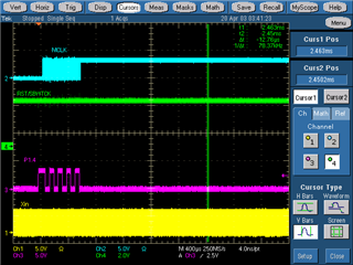
    Image from the oscilloscope when the code gets stuck:

    • MCLK: Output from the MCLK pin. It starts at around 800kHz and then stays high, but it should switch to 24MHz.
    • Reset signal: High.
    • P1.4 pin: Toggles when checking for oscillator faults
    • Xin: 24MHz.

    If you apply a little heat to the MCU with a heat gun, or simply allow the device to warm up, it starts working normally from the point where it was stuck

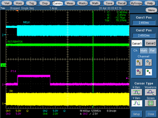
    Sometimes the MCU gets stuck, while other times it works correctly after a reset. This is the waveform from the oscilloscope when everything is functioning properly, a we can see a change from 800 kHz to 24 MHz in the MCLK waveform

    Definitely, TI experts should step in to review and provide feedback on both your and our actions. In our case, we cannot explain why it happens, why it gets stuck for a while and then starts working again, but does not reset itself. Perhaps the GPIO pin could help you identify the point where it gets stuck, it could be a great tricks in troubleshooting.

  • Few comments from myside:

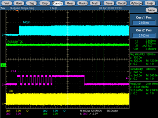
    1. could you help to capture the in clock signal capture to make sure the quality is good? 

    2. You can try this code, I have verify it with a 5.333MHz signal input(generate by a LP-MSPM0G3507 that from a timer's PWM output the duty cycle is 57%) with no issue to a MSP430FR2355


    6518.main.c
    /* --COPYRIGHT--,BSD_EX
     * Copyright (c) 2016, Texas Instruments Incorporated
     * All rights reserved.
     *
     * Redistribution and use in source and binary forms, with or without
     * modification, are permitted provided that the following conditions
     * are met:
     *
     * *  Redistributions of source code must retain the above copyright
     *    notice, this list of conditions and the following disclaimer.
     *
     * *  Redistributions in binary form must reproduce the above copyright
     *    notice, this list of conditions and the following disclaimer in the
     *    documentation and/or other materials provided with the distribution.
     *
     * *  Neither the name of Texas Instruments Incorporated nor the names of
     *    its contributors may be used to endorse or promote products derived
     *    from this software without specific prior written permission.
     *
     * THIS SOFTWARE IS PROVIDED BY THE COPYRIGHT HOLDERS AND CONTRIBUTORS "AS IS"
     * AND ANY EXPRESS OR IMPLIED WARRANTIES, INCLUDING, BUT NOT LIMITED TO,
     * THE IMPLIED WARRANTIES OF MERCHANTABILITY AND FITNESS FOR A PARTICULAR
     * PURPOSE ARE DISCLAIMED. IN NO EVENT SHALL THE COPYRIGHT OWNER OR
     * CONTRIBUTORS BE LIABLE FOR ANY DIRECT, INDIRECT, INCIDENTAL, SPECIAL,
     * EXEMPLARY, OR CONSEQUENTIAL DAMAGES (INCLUDING, BUT NOT LIMITED TO,
     * PROCUREMENT OF SUBSTITUTE GOODS OR SERVICES; LOSS OF USE, DATA, OR PROFITS;
     * OR BUSINESS INTERRUPTION) HOWEVER CAUSED AND ON ANY THEORY OF LIABILITY,
     * WHETHER IN CONTRACT, STRICT LIABILITY, OR TORT (INCLUDING NEGLIGENCE OR
     * OTHERWISE) ARISING IN ANY WAY OUT OF THE USE OF THIS SOFTWARE,
     * EVEN IF ADVISED OF THE POSSIBILITY OF SUCH DAMAGE.
     *
     *******************************************************************************
     *
     *                       MSP430 CODE EXAMPLE DISCLAIMER
     *
     * MSP430 code examples are self-contained low-level programs that typically
     * demonstrate a single peripheral function or device feature in a highly
     * concise manner. For this the code may rely on the device's power-on default
     * register values and settings such as the clock configuration and care must
     * be taken when combining code from several examples to avoid potential side
     * effects. Also see www.ti.com/grace for a GUI- and www.ti.com/msp430ware
     * for an API functional library-approach to peripheral configuration.
     *
     * --/COPYRIGHT--*/
    //******************************************************************************
    //  MSP430FR235x Demo - Configure MCLK for 16MHz operation, and XT1 sourcing
    //                                     FLLREF and ACLK.
    //
    //  Description: Configure MCLK for 16MHz. FLL reference clock is XT1. At this
    //                    speed, the FRAM requires wait states.
    //                    ACLK = XT1 ~32768Hz, SMCLK = MCLK = 16MHz.
    //                    Toggle LED to indicate that the program is running.
    //
    //           MSP430FR2355
    //         ---------------
    //        |               |
    //        |            XIN|--
    //     /|\|               |  ~32768Hz
    //      | |           XOUT|--
    //      --|RST            |
    //        |          P1.2 |---> LED
    //        |               |
    //        |          P1.0 |---> SMCLK = 16MHz
    //        |          P1.1 |---> ACLK  = 32768Hz
    //
    //
    //   Darren Lu
    //   Texas Instruments Inc.
    //   Oct. 2016
    //   Built with IAR Embedded Workbench v6.50 & Code Composer Studio v6.2
    //******************************************************************************
    #include <msp430.h>
    
    int main(void)
    {
        WDTCTL = WDTPW | WDTHOLD;                    // Stop watchdog timer
    
        // Configure one FRAM waitstate as required by the device datasheet for MCLK
        // operation beyond 8MHz _before_ configuring the clock system.
        FRCTL0 = FRCTLPW | NWAITS_1;
    
        P2SEL1 |= BIT7;                       // P2.6~P2.7: crystal pins
    
        CSCTL6 |= XTS_1 | XT1BYPASS | XT1HFFREQ_1 | XT1AGCOFF;
    
        do
        {
            CSCTL7 &= ~(XT1OFFG | DCOFFG);           // Clear XT1 and DCO fault flag
            SFRIFG1 &= ~OFIFG;
        } while (SFRIFG1 & OFIFG);                   // Test oscillator fault flag


        CSCTL4 = SELMS__XT1CLK | SELA__REFOCLK;   // set XT1 (~32768Hz) as ACLK source, ACLK = 32768Hz
                                                     // default DCOCLKDIV as MCLK and SMCLK source
    
        P1DIR |= BIT0 | BIT1 | BIT2;                 // set ACLK SMCLK and LED pin as output
        P1SEL1 |= BIT0 | BIT1;                       // set ACLK and  SMCLK pin as second function
    
        PM5CTL0 &= ~LOCKLPM5;                        // Disable the GPIO power-on default high-impedance mode
                                                     // to activate previously configured port settings
    
        while(1)
        {
            P1OUT ^= BIT2;                           // Toggle P1.2 using exclusive-OR
            __delay_cycles(8000000);                 // Delay for 80000*(1/MCLK)=0.5s
        }
    }


**Attention** This is a public forum