Tool/software:
Hello,
I am generating the PWM pulse from the Tb0.4.
param.clockSource = TIMER_B_CLOCKSOURCE_SMCLK;
param.clockSourceDivider = TIMER_B_CLOCKSOURCE_DIVIDER_4;
param.timerPeriod = timePeriod-1;
param.timerInterruptEnable_TBIE = TIMER_B_CCIE_CCR0_INTERRUPT_DISABLE;
param.captureCompareInterruptEnable_CCR0_CCIE =
TIMER_B_CCIE_CCR0_INTERRUPT_DISABLE;
param.timerClear = TIMER_B_DO_CLEAR;
param.startTimer = false;
Timer_B_initUpMode(TIMER_B0_BASE, ¶m);
//Initialize compare mode to generate PWM1
param1.compareRegister = TIMER_B_CAPTURECOMPARE_REGISTER_4;
param1.compareInterruptEnable = TIMER_B_CCIE_CCR0_INTERRUPT_DISABLE;
param1.compareOutputMode = TIMER_B_OUTPUTMODE_SET_RESET;
param1.compareValue = timePeriod*0;
Timer_B_initCompareMode(TIMER_B0_BASE, ¶m1);
At every 100us, I have to change the duty cycle 0% to 100% (compare value). Using TimerA0 to generate the 100us loop.
#pragma vector = TIMER0_A0_VECTOR
__interrupt void Timer0_A0_ISR (void){

#if 1
    if(flag==1)
    {

        if(dCuS<50)
        {
            Dutycycle=(timePeriod*dcArray1[dCuS]);
            if(Dutycycle!=0)
            {

                Timer_B_setCompareValue(TB0_BASE,TIMER_B_CAPTURECOMPARE_REGISTER_4,(uint16_t)Dutycycle);
                dCuS+=1;
            }
            else
            {

                Timer_B_setCompareValue(TB0_BASE,TIMER_B_CAPTURECOMPARE_REGISTER_4,0);
                dCuS+=1;
            }
        }
        else
        {
            Timer_B_setCompareValue(TB0_BASE,TIMER_B_CAPTURECOMPARE_REGISTER_4,timePeriod*0.50);

            dCuS=1;
        }

        count+=1;
    }
#endif

    Timer_A_clearTimerInterrupt(TIMER_A0_BASE);
}
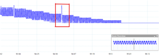
When I every the waveform in scope, I observed the one dip/spike in the PWM generation and it is affecting the my overall waveform.

How to rectify this?
Regards,
Sarwath

