This thread has been locked.

If you have a related question, please click the "Ask a related question" button in the top right corner. The newly created question will be automatically linked to this question.

MSP430G2553: MSP boot + single application

Part Number: MSP430G2553
Other Parts Discussed in Thread: CC3235SF, MSP430G2533, MSP-EXP430G2ET

Tool/software:

Hi TI support team,


I want to integrate an OTA firmware update feature into MSP430G2553. I have read application note on MSP boot and followed the steps as given in this document -> www.ti.com/.../slaa600e.pdf

I can't use BSL directly because of hardware pin config being used in deployed cards. I am using UART channel for the firmware update. In this example code, first we need to flash MSP boot firmware to target(MSP430G2553) and then host(MSP430G2553) write the new application image to target device. My requirement is different from this. 

My host device is cc3235sf which is communicating with MSP430G2553 over RS485. Now instead of flashing only MSP-boot firmware to target, I want to develop and flash a single firmware which will contain bootloader + one application in first time. So, application will run in 1st time and later, i can update the new application into msp430g2533 when required.
I want to configure CPU at 16Mhz but in example code 8mhz is being used. According to -> MSP430G2553 Microcontroller Errata (Rev. K) ,We can't change  internal clock frequency in one go, after once configured. If we do say then clock may halt or will not be configured properly. Then we need to go step by step by reading and setting RSEL. Could you please provide some example code for this if we want to config clock frequency after INIT? 
 
Kindly help me in this matter for both OTA feature and clock configuration after initialization.

  • Hi VINOD KUMAR

    MSPboot example code link on the slaa600e has been broken. Please find the mspboot on link 

    On the Errata, May I confirm if you point to BCL12?

    On clock configuration to 16MHz, please check DCO = 16MHz example code on msp430g2xx3_dco_calib.c of https://www.ti.com/tool/download/SLAC485

    Thanks!

  • Hi Xiaodong LI,

    I am referring to BCL12. could you please confirm if the code below will work fine?

    Example :

    void Clock_init(void)
    {
    if( ((BCSCTL1 & 0x0F) > 13) && ((CALDCO_1MHZ & 0x0F) < 12) )
    {
    BCSCTL1 = ((BCSCTL1 & 0xF0) | 0x0D);
    }
    else if( ((BCSCTL1 & 0x0F) < 12) && ((CALDCO_1MHZ & 0x0F) > 13) )
    {
    BCSCTL1 = ((BCSCTL1 & 0xF0) | 0x07);
    }
    else if((BCSCTL1 & 0x0F) == 0x0F)
    {
    BCSCTL1 = ((BCSCTL1 & 0xF0) | 0x07);
    }

    if (CALBC1_16MHZ == 0xFF) // If calibration constant erased
    {
    while (1); // do not load, trap CPU!!
    }

    DCOCTL = 0; // Select lowest DCOx and MODx settings
    BCSCTL1 = (CALBC1_16MHZ & 0xCF); // Set DCO
    DCOCTL = CALDCO_16MHZ;
    BCSCTL3 = LFXT1S1+ XCAP0;

    }

     
    Could you please explain how to flash the microcontroller with the MSP bootloader (UART bootloader) and the application as a single(merged) .txt file?

  • Hi VINOD KUMAR

    I compared the 16MHz clock setting code on msp430g2xx3_dco_calib.c

    it is 

    //16Mhz
    if (CALBC1_16MHZ==0xFF) // If calibration constant erased
    {
    while(1); // do not load, trap CPU!!
    }
    DCOCTL = 0; // Select lowest DCOx and MODx settings
    BCSCTL1 = CALBC1_16MHZ; // Set range
    DCOCTL = CALDCO_16MHZ; // Set DCO step + modulation*/

    I can double check if this part of code can work fine. 

    I need some time to prepare the MSP-EXP430G2ET

    I will feedback the test result later

    Thanks

  • Hi ,

    I wanted to check in regarding the example code for the workaround related to BCL12 in the MSP430 errata. I understand that you may need more time, but I’d greatly appreciate any updates when you’re able to provide them.

    Additionally,In the MSPBOOT example, 16 bytes of data are being written to flash. How can we write 64 bytes of data using the block write option in flash? Could you please advise on the necessary changes required?

  • Hi VINOD KUMAR

    >> but I’d greatly appreciate any updates when you’re able to provide them

    Thanks for your understand!

    >> Block write, Could you please advise on the necessary changes required?

    flash write mode includes byte or write mode and Block write mode separated by FCTL1.BLKWRT is 1 or not. Please refer to 7.4.1 FCTL1 Register of UM

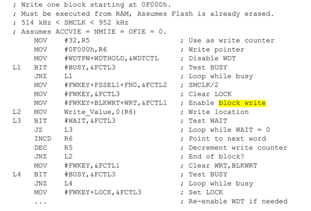
    Please find the flow and example code (ASM with comment) at 7.3.3.5 Block Write Flow and Example chapter of UM

    MOV #FWKEY+BLKWRT+WRT,&FCTL1 ; Enable block write

    This code is additionally needed for Block write mode.

  • Dear Xiaodong LI,

    Thanks for the reply!

    I am currently working on the conversion of a .txt file to a C array using the MSPBoot utility for the MSP430G2553. After conversion, I noticed that the number of array elements seems to remain fixed regardless of the size of the application or the .txt file used.

    Specifically, I am trying to increase the size of the application from 8KB to 14KB, but after the conversion, I still observe only 3 segments in the resulting C array (e.g., App1_Addr[3], App1_Size[3]).

    My question is whether there is any guarantee that only 3 elements will be present in the array after the conversion, or is this behavior dependent on some configuration or limitation within the MSPBoot utility?

    Looking forward to your insights!

  • Hi VINOD KUMAR

    The expert from our team will support your question as well.

    Thanks

  • Hi Xiaodong LI,

    Could you please provide further assistance with block write mode? I need a C code example for writing to flash memory using block write mode. Since a block write cannot be initiated from within flash memory, it must be triggered from RAM. How can we place a function in RAM using a bootloader or by modifying the linker file generated by the MSPBoot project creator utility?

    Additionally, I would appreciate further help with my previous question regarding the number of segments after converting a .txt file into a C array


    Thanks

  • My question is whether there is any guarantee that only 3 elements will be present in the array after the conversion, or is this behavior dependent on some configuration or limitation within the MSPBoot utility?

    For the segments number is depends on how many of @address exist in the .txt firmware as below

    For the lock write we do have provide a assembly code in our user's guide  as below

    Here is what I convert the code to assembly code but not tested yet, you can try it


    while (FCTL3 & BUSY); // Wait until flash controller ready (L1 loop equivalent)
    /* Flash Timing Configuration */
    FCTL2 = FWKEY | FSSEL1 | FN0; // Clock source = SMCLK/2
    FCTL3 = FWKEY; // Clear LOCK bit for write access
    /* Block Write Mode Activation */
    FCTL1 = FWKEY | BLKWRT | WRT; // Enable block write mode (Equivalent to MOV #FWKEY+BLKWRT+WRT,&FCTL1)
    /* Main Write Operation Loop */
    do {
    *write_ptr = Write_Value; // Write data to flash (MOV Write_Value,0(R6))
    /* Write Cycle Synchronization */
    while (!(FCTL3 & WAIT)); // Wait for flash controller ready (L3 loop equivalent)

    write_ptr++; // Increment write pointer (INCD R6 equivalent)

    } while (--write_counter); // Loop control (DEC R5 & JNZ L2 equivalent)
    /* Post-Write Cleanup */
    FCTL1 = FWKEY; // Clear write mode flags (Equivalent to MOV #FWKEY,&FCTL1)
    /* Final Status Verification */
    while (FCTL3 & BUSY); // Confirm operation completion (L4 loop equivalent)
    /* Flash Protection Reset */
    FCTL3 = FWKEY | LOCK; // Re-enable flash security (Equivalent to MOV #FWKEY+LOCK,&FCTL3)

  • Hi Gary Gao,

    1. Number of Segments

    Here’s my understanding regarding the number of segments, based on the example below:

    // C array after conversion from .txt to C array using MSPBoot utility
    const uint16_t App1_Addr[3] =
    {
    0xc002, // Address segment0
    0xfbc2, // Address segment1
    0xfbfe, // Address segment2
    };

    const uint16_t App1_Size[3] =
    {
    244, // Size segment0
    52, // Size segment1
    2, // Size segment2
    };
    • 0xc002 – Start of the application, size: 244
    • 0xfbc2 – Interrupt Proxy Table, size: 2
    • 0xfbfe – Application Reset Vector, size: 2

    This information was derived from the MSP430G2553 UART bootloader example code for MSPBoot. All of the above information is stored in the linker file. If we don’t make any changes, we will always have three elements after converting from TI’s .txt file to the C array.


    2. Flash Write in Block Write Mode

    Regarding the code you provided for flash write in block write mode: It works correctly only when executed from RAM. To place the function into RAM, I’m using the following attribute:

    __attribute__((ramfunc)) uint8_t TI_MSPBoot_MI_FLASH_BLOCK_Write(uint16_t *addr, uint16_t *data)
    {
    // Function implementation
    }

    Is this the correct way to proceed?

    Currently, I am able to flash the application once, but it doesn't work afterward. This is because the function resides in RAM and will work only if the location used by this function remains unchanged. Therefore, the function should be placed at a specific location in RAM. Additionally, this location should be reserved and protected from being altered by the application code.

    Could you kindly help me ensure this function is placed at a fixed RAM location? Also, I need guidance on ensuring that this location is protected, so it doesn't get overwritten by the application code. Ideally, this information should be reflected in the linker files for both the bootloader and application projects.


    Thanks.

  • This information was derived from the MSP430G2553 UART bootloader example code for MSPBoot. All of the above information is stored in the linker file. If we don’t make any changes, we will always have three elements after converting from TI’s .txt file to the C array.

    For this file is used by the host MCU easy to call in C code that need to downloaded into the target MCU. It is not has any affect to linker file. And you do not need to care how many elements it is, it will be handled by the host.

    You can try this to fix a function at a specific address

    To avoid application code to used some memory area, like some RAM area you needed above, you can just to modify the linker file(cmd file in CCS) to make sure the application linker file not include the RAM area you used above will be ok. 

    For example If the device RAM is from 0x2000 to 0x2300, and you need 0x100 for special use, so you can define the RAM as below in the cmd

**Attention** This is a public forum