This thread has been locked.

If you have a related question, please click the "Ask a related question" button in the top right corner. The newly created question will be automatically linked to this question.

MSP430FR2475: Unknown I2C slave address read

Part Number: MSP430FR2475
Other Parts Discussed in Thread: TCA9543A, TCA9534A

Tool/software:

Hi Team,

I am using MSP430-FR-2475 MCU as a I2C master with 400Khz  speed and one I2C slave is connected to it with unknown slave address. 

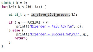
Can you please suggest the exact code to know the I2C slave address of this slave device?

Generally we have to provide start I2C, then send address values one by one in for loop and whichever address value is acknowleged is considered as slave address. But in firmware exactly how to implement this i am confused. Can you please help here?

  • Below i am sharing the I2C codes i have in firmware for two I2C channels I2C and I2C1.

    /* Used to track the state of the software state machine*/
    I2C_Mode MasterMode = IDLE_MODE;

    /* The Register Address/Command to use*/
    uint8_t TransmitRegAddr = 0;

    /* ReceiveBuffer: Buffer used to receive data in the ISR */
    uint8_t ReceiveBuffer[MAX_BUFFER_SIZE] = {0};

    /* RXByteCtr: Number of bytes left to receive */
    uint8_t RXByteCtr = 0;

    /* ReceiveIndex: The index of the next byte to be received in ReceiveBuffer */
    uint8_t ReceiveIndex = 0;

    /* TransmitBuffer: Buffer used to transmit data in the ISR */
    uint8_t TransmitBuffer[MAX_BUFFER_SIZE] = {0};

    /* TXByteCtr: Number of bytes left to transfer */
    static uint8_t TXByteCtr = 0;

    /* TransmitIndex: The index of the next byte to be transmitted in TransmitBuffer */
    uint8_t TransmitIndex = 0;

    uint8_t first_byte_received = 1,PD_Communication;

    extern uint8_t bay_id;

    //******************************************************************************

    /***************************** Function definition *****************************/

    /**
    * @brief
    * Initilization of I2C0
    *
    * @details
    * Initilization of I2C0
    *
    * @param[in] None
    *
    * @return None
    */
    void initI2C(void)
    {
    UCB0CTLW0 = UCSWRST; // Enable SW reset
    UCB0CTLW0 |= UCMODE_3 | UCMST | UCSSEL__SMCLK | UCSYNC; // I2C master mode, SMCLK

    #if I2C_SPEED_400KHZ
    UCB0BRW = 40; // fSCL = SMCLK/40 = ~400kHz
    #else
    UCB0BRW = 160; // fSCL = SMCLK/160 = ~100kHz
    #endif
    UCB0I2CSA = SLAVE_ADDR_TEMP_I2C0; // Slave Address
    UCB0CTLW0 &= ~UCSWRST; // Clear SW reset, resume operation
    UCB0IE |= UCNACKIE;
    }


    /**
    * @brief
    * Initilization of I2C1
    *
    * @details
    * Initilization of I2C1
    *
    *
    * @param[in] None
    *
    * @return None
    */
    void initI2C1(void)
    {
    UCB1CTLW0 = UCSWRST; // Enable SW reset
    UCB1CTLW0 |= UCMODE_3 | UCMST | UCSSEL__SMCLK | UCSYNC; // I2C master mode, SMCLK

    #if I2C_SPEED_400KHZ
    UCB1BRW = 40; // fSCL = SMCLK/40 = ~400kHz
    #else
    UCB1BRW = 160; // fSCL = SMCLK/160 = ~100kHz
    #endif
    UCB1I2CSA = SLAVE_ADDR_TEMP_I2C1; // Slave Address
    UCB1CTLW0 &= ~UCSWRST; // Clear SW reset, resume operation
    UCB1IE |= UCNACKIE;
    }


    /* For slave device with dev_addr, read the data specified in slaves reg_addr for I2C0.
    * The received data is available in ReceiveBuffer
    *
    * dev_addr: The slave device address.
    * Example: SLAVE_ADDR
    * reg_addr: The register or command to send to the slave.
    * Example: CMD_TYPE_0_SLAVE
    * count: The length of data to read
    * Example: TYPE_0_LENGTH
    * @return: I2C mode
    */
    I2C_Mode I2C_Master_ReadReg(uint8_t dev_addr, uint8_t reg_addr, uint8_t count)
    {
    delay(10);
    /* Initialize state machine */
    MasterMode = TX_REG_ADDRESS_MODE;
    TransmitRegAddr = reg_addr;
    RXByteCtr = count;
    TXByteCtr = 0;
    ReceiveIndex = 0;
    TransmitIndex = 0;

    /* Initialize slave address and interrupts */
    UCB0I2CSA = dev_addr;
    UCB0IFG &= ~(UCTXIFG + UCRXIFG); // Clear any pending interrupts
    UCB0IE &= ~UCRXIE; // Disable RX interrupt
    UCB0IE |= UCTXIE; // Enable TX interrupt

    UCB0CTLW0 |= UCTR + UCTXSTT; // I2C TX, start condition

    if ( (dev_addr == SLAVE_ADDR_PD) || (dev_addr == SLAVE_ADDR_PD_PORT2) ) {

    __bis_SR_register(GIE);
    #if I2C_SPEED_400KHZ
    delay(5);
    #else
    delay(50);
    #endif

    } else {

    __bis_SR_register(LPM0_bits + GIE);

    }

    return MasterMode;
    }


    /* For slave device with dev_addr, writes the data specified in *reg_data for I2C0.
    *
    * dev_addr: The slave device address.
    * Example: SLAVE_ADDR
    * reg_addr: The register or command to send to the slave.
    * Example: CMD_TYPE_0_MASTER
    * *reg_data: The buffer to write
    * Example: MasterType0
    * count: The length of *reg_data
    * Example: TYPE_0_LENGTH
    * @return: I2C mode
    */
    I2C_Mode I2C_Master_WriteReg(uint8_t dev_addr, uint8_t reg_addr, uint8_t *reg_data, uint8_t count)
    {
    delay(10);
    /* Initialize state machine */
    MasterMode = TX_REG_ADDRESS_MODE;
    TransmitRegAddr = reg_addr;

    //Copy register data to TransmitBuffer
    #if ENABLE_CopyArray_API
    CopyArray(reg_data, TransmitBuffer, count);
    #else
    memcpy(TransmitBuffer, reg_data, count);
    #endif // ENABLE_CopyArray_API

    TXByteCtr = count;
    RXByteCtr = 0;
    ReceiveIndex = 0;
    TransmitIndex = 0;

    /* Initialize slave address and interrupts */
    UCB0I2CSA = dev_addr;
    UCB0IFG &= ~(UCTXIFG + UCRXIFG); // Clear any pending interrupts
    UCB0IE &= ~UCRXIE; // Disable RX interrupt
    UCB0IE |= UCTXIE; // Enable TX interrupt

    UCB0CTLW0 |= UCTR + UCTXSTT; // I2C TX, start condition

    if ( (dev_addr == SLAVE_ADDR_PD) || (dev_addr == SLAVE_ADDR_PD_PORT2) ) {

    __bis_SR_register(GIE);
    #if I2C_SPEED_400KHZ
    delay(5);
    #else
    delay(50);
    #endif

    } else {

    __bis_SR_register(LPM0_bits + GIE);

    }

    return MasterMode;
    }

    /* For slave device with dev_addr, writes the data specified in *reg_data for I2C1
    *
    * dev_addr: The slave device address.
    * Example: SLAVE_ADDR
    * reg_addr: The register or command to send to the slave.
    * Example: CMD_TYPE_0_MASTER
    * *reg_data: The buffer to write
    * Example: MasterType0
    * count: The length of *reg_data
    * Example: TYPE_0_LENGTH
    * @return: I2C mode
    */
    I2C_Mode I2C_Master_WriteReg1(uint8_t dev_addr, uint8_t reg_addr, uint8_t *reg_data, uint8_t count)
    {
    delay(10);
    /* Initialize state machine */
    MasterMode = TX_REG_ADDRESS_MODE;
    TransmitRegAddr = reg_addr;

    //Copy register data to TransmitBuffer
    #if ENABLE_CopyArray_API
    CopyArray(reg_data, TransmitBuffer, count);
    #else
    memcpy(TransmitBuffer, reg_data, count);
    #endif // ENABLE_CopyArray_API

    TXByteCtr = count;
    RXByteCtr = 0;
    ReceiveIndex = 0;
    TransmitIndex = 0;

    /* Initialize slave address and interrupts */
    UCB1I2CSA = dev_addr;
    UCB1IFG &= ~(UCTXIFG + UCRXIFG); // Clear any pending interrupts
    UCB1IE &= ~UCRXIE; // Disable RX interrupt
    UCB1IE |= UCTXIE; // Enable TX interrupt

    UCB1CTLW0 |= UCTR + UCTXSTT; // I2C TX, start condition
    __bis_SR_register(LPM0_bits + GIE); // Enter LPM0 w/ interrupts

    return MasterMode;
    }


    /* For slave device with dev_addr, read the data specified in slaves reg_addr for I2C1.
    * The received data is available in ReceiveBuffer
    *
    * dev_addr: The slave device address.
    * Example: SLAVE_ADDR
    * reg_addr: The register or command to send to the slave.
    * Example: CMD_TYPE_0_SLAVE
    * count: The length of data to read
    * Example: TYPE_0_LENGTH
    * @return: I2C mode
    */
    I2C_Mode I2C_Master_ReadReg1(uint8_t dev_addr, uint8_t reg_addr, uint8_t count)
    {
    delay(10);
    /* Initialize state machine */
    MasterMode = TX_REG_ADDRESS_MODE;
    TransmitRegAddr = reg_addr;
    RXByteCtr = count;
    TXByteCtr = 0;
    ReceiveIndex = 0;
    TransmitIndex = 0;

    /* Initialize slave address and interrupts */
    UCB1I2CSA = dev_addr;
    UCB1IFG &= ~(UCTXIFG + UCRXIFG); // Clear any pending interrupts
    UCB1IE &= ~UCRXIE; // Disable RX interrupt
    UCB1IE |= UCTXIE; // Enable TX interrupt

    UCB1CTLW0 |= UCTR + UCTXSTT; // I2C TX, start condition
    __bis_SR_register(LPM0_bits + GIE); // Enter LPM0 w/ interrupts

    return MasterMode;
    }


    /**
    * @brief
    * Copy data from one buffer to another.
    *
    * @details
    * Copy data from one buffer to another.
    *
    * @param[in] source source buffer
    * @param[in] dest destination buffer
    * @param[in] count number of bytes to be transferred.
    *
    * @return None.
    */
    #if ENABLE_CopyArray_API
    void CopyArray(uint8_t *source, uint8_t *dest, uint8_t count)
    {
    uint8_t copyIndex = 0;
    for ( copyIndex = 0; copyIndex < count; copyIndex++ ) {
    dest[copyIndex] = source[copyIndex];
    }
    }
    #endif //#if ENABLE_CopyArray_API

    /**
    * @brief
    * Checking of slave on i2c0.
    *
    * @details
    * Checking of slave on i2c0.
    *
    * @param[in] NA
    *
    * @return success or failure.
    */
    uint8_t is_slave_i2c0_present(void)
    {
    unsigned char slaveadr_bak, ucb0i2cie;
    uint8_t returnValue;
    ucb0i2cie = UCB0IE; // restore old UCB0I2CIE
    slaveadr_bak = UCB0I2CSA; // store old slave address
    UCB0IE &= ~ UCNACKIE; // no NACK interrupt
    UCB0I2CSA = SLAVE_ADDR_TEMP_I2C0; // set slave address
    UCB0IE &= ~(UCTXIE0 + UCRXIE0); // no RX or TX interrupts
    UCB0CTLW0 |= UCTR + UCTXSTT + UCTXSTP; // I2C TX, start condition
    while (UCB0CTLW0 & UCTXSTP); // wait for STOP condition

    if (UCB0IFG & UCNACKIFG) {
    returnValue = FAILURE;
    } else {
    returnValue = SUCCESS;
    }

    UCB0I2CSA = slaveadr_bak; // restore old slave address
    UCB0IE = ucb0i2cie; // restore old UCB0CTL1
    return returnValue; // return whether or not // a NACK occured
    }


    /**
    * @brief
    * Checking of slave on i2c1.
    *
    * @details
    * Checking of slave on i2c1.
    *
    * @param[in] NA
    *
    * @return success or failure.
    */
    uint8_t is_slave_i2c1_present(void)
    {
    unsigned char slaveadr_bak, ucb1i2cie;
    uint8_t returnValue;
    ucb1i2cie = UCB1IE; // restore old UCB0I2CIE
    slaveadr_bak = UCB1I2CSA; // store old slave address
    UCB1IE &= ~ UCNACKIE; // no NACK interrupt

    switch ( bay_id ) {

    case SINGLE_BAY:
    UCB1I2CSA = SLAVE_ADDR_TEMP_I2C0; // set slave address
    break;

    case EIGHT_BAY:
    UCB1I2CSA = SLAVE_ADDR_TEMP_I2C1; // set slave address
    break;

    #if 0
    default:
    debug_log_invalid_bay_id();
    #endif
    }
    UCB1IE &= ~(UCTXIE + UCRXIE); // no RX or TX interrupts
    UCB1CTLW0 |= UCTR + UCTXSTT + UCTXSTP; // I2C TX, start condition
    while (UCB1CTLW0 & UCTXSTP); // wait for STOP condition

    if (UCB1IFG & UCNACKIFG) {
    returnValue = FAILURE;
    } else {
    returnValue = SUCCESS;
    }

    UCB1I2CSA = slaveadr_bak; // restore old slave address
    UCB1IE = ucb1i2cie; // restore old UCB0CTL1
    return returnValue; // return whether or not // a NACK occured
    }

    //******************************************************************************
    // I2C Interrupt ***************************************************************
    //******************************************************************************

    #if defined(__TI_COMPILER_VERSION__) || defined(__IAR_SYSTEMS_ICC__)
    #pragma vector = USCI_B0_VECTOR
    __interrupt void USCI_B0_ISR(void)
    #elif defined(__GNUC__)
    void __attribute__ ((interrupt(USCI_B0_VECTOR))) USCI_B0_ISR (void)
    #else
    #error Compiler not supported!
    #endif
    {
    //Must read from UCB0RXBUF
    uint8_t rx_val = 0;
    switch(__even_in_range(UCB0IV, USCI_I2C_UCBIT9IFG))
    {
    case USCI_NONE: break; // Vector 0: No interrupts
    case USCI_I2C_UCALIFG: break; // Vector 2: ALIFG
    case USCI_I2C_UCNACKIFG: // Vector 4: NACKIFG

    UCB0IE &= ~UCRXIE;
    MasterMode = NACK_MODE;
    first_byte_received = FALSE;
    __bic_SR_register_on_exit(CPUOFF);
    break;

    case USCI_I2C_UCSTTIFG: break; // Vector 6: STTIFG
    case USCI_I2C_UCSTPIFG: break; // Vector 8: STPIFG
    case USCI_I2C_UCRXIFG3: break; // Vector 10: RXIFG3
    case USCI_I2C_UCTXIFG3: break; // Vector 12: TXIFG3
    case USCI_I2C_UCRXIFG2: break; // Vector 14: RXIFG2
    case USCI_I2C_UCTXIFG2: break; // Vector 16: TXIFG2
    case USCI_I2C_UCRXIFG1: break; // Vector 18: RXIFG1
    case USCI_I2C_UCTXIFG1: break; // Vector 20: TXIFG1
    case USCI_I2C_UCRXIFG0: // Vector 22: RXIFG0
    rx_val = UCB0RXBUF;
    #if 1
    if ( PD_Communication == TRUE ) {
    PD_Communication = FALSE;
    RXByteCtr = rx_val; /* In read operation the first byte received will be the length */
    }
    #endif
    if ( RXByteCtr ) {
    ReceiveBuffer[ReceiveIndex++] = rx_val;
    RXByteCtr--;
    }

    if ( RXByteCtr == 1 ) {
    UCB0CTLW0 |= UCTXSTP;
    } else if ( RXByteCtr == 0 ) {
    UCB0IE &= ~UCRXIE;
    MasterMode = IDLE_MODE;
    first_byte_received = FALSE;
    __bic_SR_register_on_exit(CPUOFF); // Exit LPM0
    }
    break;

    case USCI_I2C_UCTXIFG0: // Vector 24: TXIFG0
    switch ( MasterMode ) {
    case TX_REG_ADDRESS_MODE:
    UCB0TXBUF = TransmitRegAddr;
    if (RXByteCtr)
    MasterMode = SWITCH_TO_RX_MODE; // Need to start receiving now
    else
    MasterMode = TX_DATA_MODE; // Continue to transmision with the data in Transmit Buffer
    break;

    case SWITCH_TO_RX_MODE:
    UCB0IE |= UCRXIE; // Enable RX interrupt
    UCB0IE &= ~UCTXIE; // Disable TX interrupt
    UCB0CTLW0 &= ~UCTR; // Switch to receiver
    MasterMode = RX_DATA_MODE; // State state is to receive data
    UCB0CTLW0 |= UCTXSTT; // Send repeated start
    if ( RXByteCtr == 1 ) {

    //Must send stop since this is the N-1 byte
    while((UCB0CTLW0 & UCTXSTT));
    UCB0CTLW0 |= UCTXSTP; // Send stop condition
    first_byte_received = FALSE;
    }
    break;

    case TX_DATA_MODE:
    if (TXByteCtr) {
    UCB0TXBUF = TransmitBuffer[TransmitIndex++];
    TXByteCtr--;
    } else {
    //Done with transmission
    UCB0CTLW0 |= UCTXSTP; // Send stop condition
    MasterMode = IDLE_MODE;
    UCB0IE &= ~UCTXIE; // disable TX interrupt
    __bic_SR_register_on_exit(CPUOFF); // Exit LPM0
    }
    break;

    default:
    __no_operation();
    break;
    }
    break;
    default: break;
    }
    }

    //******************************************************************************
    // I2C1 Interrupt ***************************************************************
    //******************************************************************************
    #if defined(__TI_COMPILER_VERSION__) || defined(__IAR_SYSTEMS_ICC__)
    #pragma vector = USCI_B1_VECTOR
    __interrupt void USCI_B1_ISR(void)
    #elif defined(__GNUC__)
    void __attribute__ ((interrupt(USCI_B1_VECTOR))) USCI_B1_ISR (void)
    #else
    #error Compiler not supported!
    #endif
    {
    //Must read from UCB1RXBUF
    uint8_t rx_val = 0;
    switch(__even_in_range(UCB1IV, USCI_I2C_UCBIT9IFG)) {

    case USCI_NONE: break; // Vector 0: No interrupts
    case USCI_I2C_UCALIFG: break; // Vector 2: ALIFG
    case USCI_I2C_UCNACKIFG: // Vector 4: NACKIFG

    UCB1IE &= ~UCRXIE;
    MasterMode = NACK_MODE;
    __bic_SR_register_on_exit(CPUOFF);
    break;

    case USCI_I2C_UCSTTIFG: break; // Vector 6: STTIFG
    case USCI_I2C_UCSTPIFG: break; // Vector 8: STPIFG
    case USCI_I2C_UCRXIFG3: break; // Vector 10: RXIFG3
    case USCI_I2C_UCTXIFG3: break; // Vector 12: TXIFG3
    case USCI_I2C_UCRXIFG2: break; // Vector 14: RXIFG2
    case USCI_I2C_UCTXIFG2: break; // Vector 16: TXIFG2
    case USCI_I2C_UCRXIFG1: break; // Vector 18: RXIFG1
    case USCI_I2C_UCTXIFG1: break; // Vector 20: TXIFG1
    case USCI_I2C_UCRXIFG0: // Vector 22: RXIFG0
    rx_val = UCB1RXBUF;
    #if 1
    if ( PD_Communication == TRUE ) {
    PD_Communication = FALSE;
    RXByteCtr = rx_val; /* In read operation the first byte received will be the length */
    }
    #endif
    if ( RXByteCtr ) {

    ReceiveBuffer[ReceiveIndex++] = rx_val;
    RXByteCtr--;
    }

    if ( RXByteCtr == 1 ) {

    UCB1CTLW0 |= UCTXSTP;
    } else if ( RXByteCtr == 0 ) {
    UCB1IE &= ~UCRXIE;
    MasterMode = IDLE_MODE;
    __bic_SR_register_on_exit(CPUOFF); // Exit LPM0
    }
    break;
    case USCI_I2C_UCTXIFG0: // Vector 24: TXIFG0
    switch ( MasterMode ) {

    case TX_REG_ADDRESS_MODE:
    UCB1TXBUF = TransmitRegAddr;
    if (RXByteCtr)
    MasterMode = SWITCH_TO_RX_MODE; // Need to start receiving now
    else
    MasterMode = TX_DATA_MODE; // Continue to transmision with the data in Transmit Buffer
    break;

    case SWITCH_TO_RX_MODE:
    UCB1IE |= UCRXIE; // Enable RX interrupt
    UCB1IE &= ~UCTXIE; // Disable TX interrupt
    UCB1CTLW0 &= ~UCTR; // Switch to receiver
    MasterMode = RX_DATA_MODE; // State state is to receive data
    UCB1CTLW0 |= UCTXSTT; // Send repeated start
    if ( RXByteCtr == 1 ) {

    //Must send stop since this is the N-1 byte
    while((UCB1CTLW0 & UCTXSTT));
    UCB1CTLW0 |= UCTXSTP; // Send stop condition
    }
    break;

    case TX_DATA_MODE:
    if ( TXByteCtr ) {

    UCB1TXBUF = TransmitBuffer[TransmitIndex++];
    TXByteCtr--;
    } else {

    //Done with transmission
    UCB1CTLW0 |= UCTXSTP; // Send stop condition
    MasterMode = IDLE_MODE;
    UCB1IE &= ~UCTXIE; // disable TX interrupt
    __bic_SR_register_on_exit(CPUOFF); // Exit LPM0
    }
    break;

    default:
    __no_operation();
    break;
    }
    break;
    default: break;
    }
    }

  • What result are you getting now?

    I don't see anything obviously wrong with your code. I do suggest:

    UCB1IE = ucb1i2cie; // restore old UCB0CTL1

    You should probably precede this with something like UCB1IFG=0 to avoid false/stale interrupt indicators.

  • Hi

    I am not sure how to use the function to know the i2c slave address from above functions. 

    I am using is_slave_i2c0_present(void) function and in that i use UCB1I2CSA = 0xE0;  // set slave address instruction to know the address, but i am getting FAILURE value. Can you please guide how to use these API?

  • hi

    This way i am iterating for() loop by incrementing and applying slave address value. When 0x20 (32 decimal) reaches, the Success is read in debug logs. Does it mean that the I2C slave address is 0x20?

  • Yes, that would be the principle -- send an empty request to each possible I2C address, and see which ones are accepted (acknowledged). If there were more than one device on the bus, each one would answer.

    Some observations:

    1) An I2C address is only 7 bits, so your device might show up twice (once at 0x20, and again at 0xA0).

    2) You should avoid probing the reserved addresses (0x00-0x07 and 0x78-0x7F) since some of them might have unexpected results.

    Combining (1)/(2), your loop bounds should be 0x08-0x77.

  • Hi

    The I2C expander TCA9543A is connected with MCU MSP-2475. Now the A1 and A0 pins both are connected with ground. Now Considering the datasheet, the address comes as 0xE0 (or 0xE1 for read). But in my code when i iterate the loop, this 0xE0 (or 0xE1) does not get detected. The connections proper from hardware side. 

    i have attached the I2C expander datasheet below.

    tca9543a.pdf

    Can you please suggest what i am missing here?

    Thanks,

    Nitish

  • An I2C address is only 7 bits. The R/W bit is not part of the address. [Ref I2C Spec (UM10204 rev 7.0) Fig 10.]

    Figures 12-13 (shown) actually say this. Fig 14/Sec 8.6.1 is incorrect. With A0=A1=0, the address you want is 0x70.

    The I2C unit ignores the high-order bit of I2CSA, so if you put 0xE0 there you're actually using address 0x60.

    ----

    Scanning the buses behind the TCA9534A is a matter of strategy. I suppose you could just write Control=0x03 and (re-)scan, though that could expose address conflicts (we suppose that the switch is there for a reason).

  • Ok. So should i consider the slave address 0x70?

  • With A0=A1=0, the address you want (for the expander itself) is 0x70, as shown in Figs 12-13.

    To scan the buses behind it you need to "know" it's there -- according to Adafruit's I2C address compendium, there are other devices which use 0x70-0x73:

    https://learn.adafruit.com/i2c-addresses/the-list

**Attention** This is a public forum