Tool/software:
Hi Team,
I have some questions on the USS configurations for the MSP430FR6043.
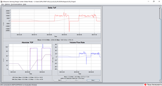
The received signal amplitude on the spool I am using is approximately +/- 250mV at 1.0dB Gain. At 7.7dB to 11.7dB gain setting, the received signal amplitude is approximately 1V which solves the problem of the amplitude of my received signal being too low. This signal is clean during zero flow. But because the gain is so high, the noisy part of the signal is also amplified and I get erroneous readings during water flow.
I would appreciate it if I could get me some insights on what the settings should be such that the amplitude of my received signal should not reduce but the erroneous sudden peaks should get managed.
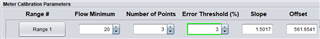
I have attached a file depicting the issue and the configured parameters on TI's USS Design Center GUI. In Summary, during zero flow, the received signal and its amplitude is clean but during flow it is very distorted.
Please Note: Audiowell Ultrasonic Sensors are being used for this test, although the spool used is NOT from Audiowell , it is of DN40 size with V-Shape Geometry configuration for the sensor placement.