This thread has been locked.

If you have a related question, please click the "Ask a related question" button in the top right corner. The newly created question will be automatically linked to this question.

EVM430-FR6047: Measuring power consumption

Part Number: EVM430-FR6047
Other Parts Discussed in Thread: TIDA-01486, MSP430FR6047

Tool/software:

We are evaluating the MSP430FR6047 system for water flow measurement using transducers that are clamped on to the outside of the pipe. We are using the EVM430-FR6047 evaluation system and also using the TIDA-01486 amplifier design to drive the trasnducers at a higher voltage in order to get a strong enough acoustic signal to penetrate metal pipes.

I am using a Keysight 34461A 6.5 digit multimeter to measure the current drawn by the MSP430FR6047 while it is measuring water flow. The ammeter is connected to J32 on the EVM430-FR6047.

As I understand it, measuring the current at J32 should measure only the current drawn by the MSP430 processor. The datasheet for the MSP430FR6047 claims that the overall current consumption is approximately 3 uA with 1 measurment per second. I am measuring approximately 116 mA with an ultrasonic measurement rate of 1 measurement per second. Am I doing something wrong? Is there a specific way to configure the MSP430 with the USS application to get 3 uA?

Also, the TIDA-01486 amplifier board draws a lot of power. This amplifier board is designed to accommodate 2 pairs of transducers, so there are 8 op amps on it. I am only using 1 pair of transducers, and so am only using 4 of the 8 op amps. The 4 op amps are consuming about 20 mA from 30 V. Is there a way to reduce the power consumption of the amplifier?

Thanks in advance for your help.

  • Hi thanks for the question! Can you share more on your specific setup? Do you also have LEDs enabled, etc. This should measure the current of the MSP, but if there are other peripherals driven by the device, this could be why you are seeing a higher current than that in the datasheet.

    -Brian

  • Hi Brian. Thanks for the response.

    I don't know what other detail to share about my setup, but I'll take a stab...

    I am using the EVM430-FR6047 standard out of the box. The only modification is the addition of the TIDA-01486 amplfier board. But the location on the EVM where I am measuring current ought not be affected by anything plugged into the booster pack headers.

    The LEDs to which you refer, are those LED1 to LED3 (from the EVM schematic?) If so, those are enabled. But if I set up my transducers on the pipe such that I get a good receive signal then all the LEDs are all off (I think - I'll have to confirm). Is there a way that I can disable those GPIOs with the USS software application?

    The MSP430FR6047 on the EVM is being powered internally, that is, it is being powered by the computer that is plugged into the USB port of the EVM.

    I'm not using the buttons but I don't know if those GPIOs are enabled.

    I'm not using the LCD. It is blank, but I don't know if the LCD port on the MSP430FR6047 is enabled or disabled.

    I am using the EZFET part of the EVM, but this ought not make the MSP430FR6047 draw any more power.

    Is this the detail you're asking for?

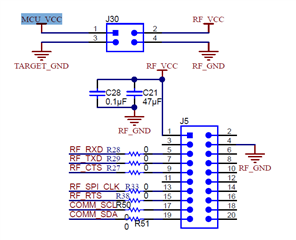
  • Hi Anthony, yes that was what I was asking. I am not sure if you can disable the LEDs (LED 1/2/3) from the GUI, but if these are not needed you could depopulate them (or the resistor) to see if this brings down the current consumption. Sounds like there is something on the board that is quietly consuming current. Do you have any jumper on J30? The MCU_VCC looks like it can be connected to the RF_VCC via this header.

  • Hi Brian;

    Yes, I can depopulate the resistors to open the LED circuits. That's easy. But won't the MSP430FR6047 draw more power (probably small) even if the GPIO blocks are enabled?

    Dang! You're right. J30 is the jumper that supplies the booster pack headers with 3.3 V. And I do have the TIDA-01486 amplifier board plugged in to it. I should be able to calculate the current drawn by the parts on the 3.3 V and subtract that total from what I'm measuring.

    Thanks for pointing that out!

  • Hey Anthony, were you able to confirm that the current drawn by the MSP is as expected now?

  • I'm working on this today. I'll have to make some further modifications to my TIDA-01486 board.

  • I think I found the problem, but I can't verify it.

    The TIDA-01486 amplifier board is set up with some switching logic and op amps to increase the functionality of the EVM430-FR4067 from 1 pair of transducers to 2 pairs of transducers. There are four different receive paths, and each of those receive paths use a bias voltage that is created from the 3.3 V power rail with foltage dividers. And the 4 voltage dividers draw a total of 105.6 uA.

    By subtracting that 105.6 uA from my measured 116 uA I get about 11 uA of operational current drawn from my 3.3 V rail. The switching and logic might draw  anout 5 uA or so. So without the amplifier board connected, I should get a pretty low measured power consumption.

**Attention** This is a public forum