This thread has been locked.

If you have a related question, please click the "Ask a related question" button in the top right corner. The newly created question will be automatically linked to this question.

external temperature sensor in ez430 rf2500

hai

i'm going to use external temperature sensor in ez430 rf2500. the sample program in sensor monitor demo is working well.. now i'm using external nasal temperature sensor which is of MLT415/A type.. i want to display the temperature using sensor monitor demo.. i dont no where to connect with msp430. plz tell me how to connect it with msp430 and what are all the pin changes that i want to made?

  • The MLT is a thermistor with a typical NTC-like characteristic.

    I don't know about the external temp sensor of the RF2500, but I think it is an NTC too.

    So see the schematics of the original sensor (head resistor or whatever) and connect the MLT similarly.

    However, the MLT has a different base resistance, so the required values for the head resistor or whatever else is atteched ned to be different, so the MSP can sample a proper signal. Also, the formula forcalculating the temperature for the measured voltage must be adjusted too.

    The nominal resistance is 10kOhm@25°C and a temperature coefficient of -4%/°C So on 26°C it is 10k-4% = 9600Ohm, on 27°C it is (10k-4%)-4% = 9216Ohm etc.
    Depending on the head resistor and the supply voltage, this gives you a voltage level on the MSP ADC input. You can try a realtime calculation or build a table. E.g. with 1024 values for all possible ADC10 readings. Excel is a good tool for building such a table. Then you can just lookup the temperature at the position x in the table if the ADC reads x as conversion result. Makes the code larger, but the execution is much faster.

    Example: supply voltage 3V, head resistor 10k, ADC reference 2,5V
    25°C: MLT resistance 10K, voltage over MLT = 3V*(10k/(10k+10k))=1.5V, ADC10 reading is 614.
    26°C: MLT resistance = 9600Ohm, voltage over MLT = 3V*(9600/(10k+9600)) = 1,469V, ADC reading is 601 etc.
    (you see, 0.1°C resolution is possible here, but this changes due to the non-linearity.
    40°C: MSL resistance = 5553Ohm, voltage over MLT = 3* (5553/(10k+5553)) = 1.071V, ADC reading is 438

  • If that's true what I read in "Wireless Sensor Monitor Using the eZ430-RF2500 (slaa378d)" the internal ADC10 temperature sensor is used in this kit.

    So you will have to "design" your own external circuit, but it should not be that hard. You'll basically need a GPIO (if you want to save some current and turn off the sensor between readings), an ADC channel and a connection to ground:

    GPIO---------RESISTOR--------o--------NTC----------GROUND
                                 |
                                ADC

    (ASCIIrcuit is great...)

  • Nice drawing.
    What's this ASCIIrcuit?

    However, due to the logarithmic behavior of the NTC resistance curve, which is even increased by the head resistor, you usually add a parallel resistor to the NTC that adds a second pole to the curve. By proper selection of this resistor, you'll get a perfect match not only on the two calibration points (lowest/highest temperature of the measured range), but also when you interpolate linearly between them, you'll get a third exact reading in the middle. Below and above the calibration/corner points, the readings go into the void fast, while between them you'll get an under/overswing.

    I ha dto go through lots of calculations (I used an Excel sheet) to find the best resistor values.
    I really don't like NTCs. PTCs like the PT1000 have a linear increase of resistance and are far better to handle.

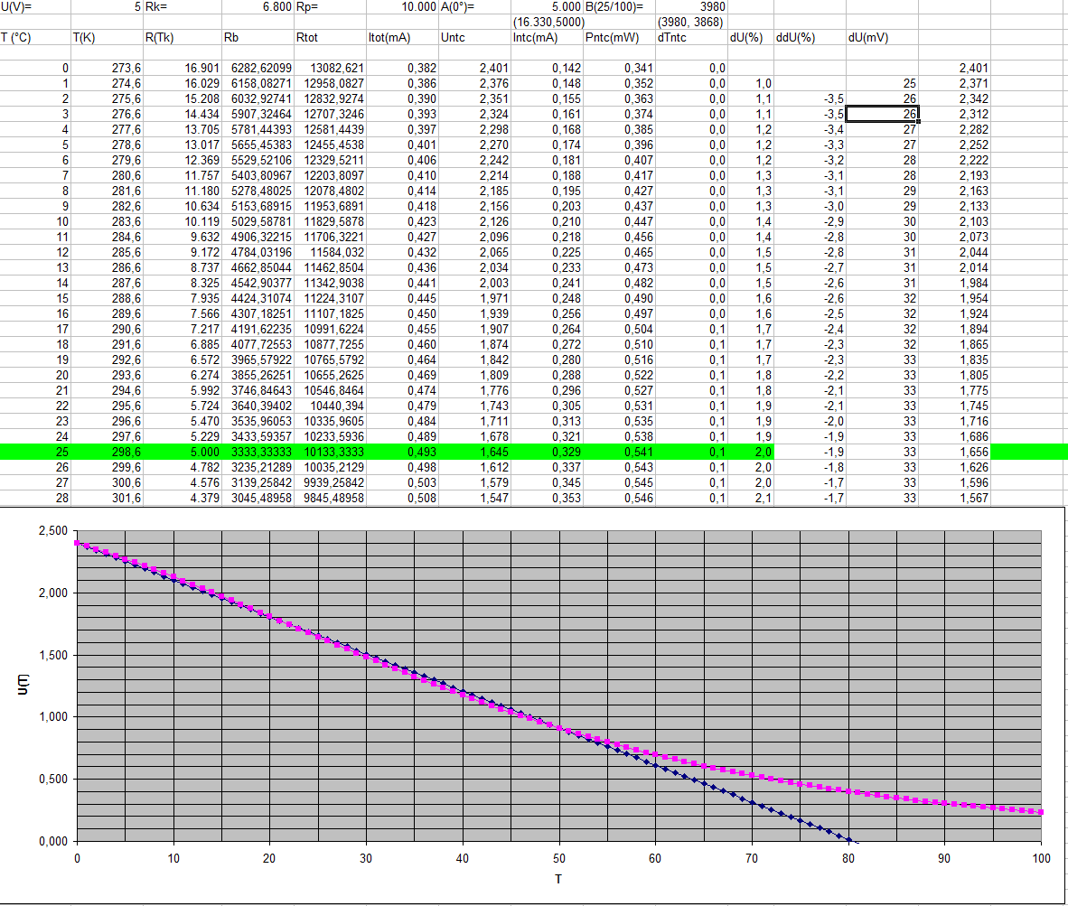
    I have attached two examples. In both, VCC is 5V. In the first one, the head resistor is 6800Ohm, the parallel resistor is 10k. THis is for measuring between 0 and 50°C.
    The NTC base resistance (on 25°C) is 5k, the 'B' is 3980 (for the logarithmic calculation)
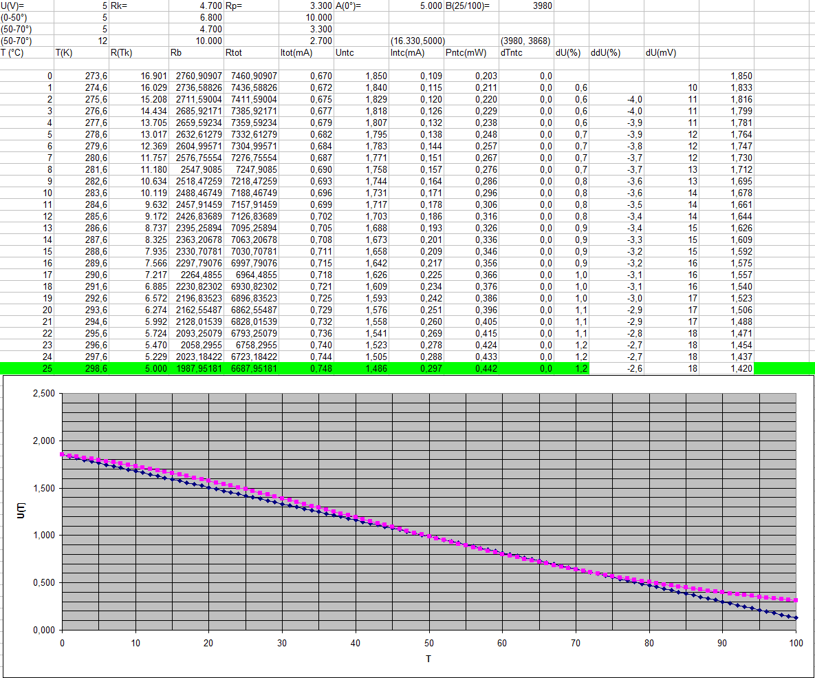
    On teh second one, wiht the same NTC, the head resistor is 4700Ohm and the parallel resitor is 3300Ohm. This time it is optimized for a 50..70°C reading.
    The blue diamonds are the interpolated line through the calibraiton points, the pink ones are the 'real' values. (voltage over temperature).

  • That is quite impressive, we used just a quadratic fit to get the temperature without a parallel resistor - but I guess it depends on the implementation and the required precision and accuracy. Also a constant current source might be a way to get an easier reading of the resistance - though of course with additional external components.

    ASCIIrcuit - it was just a funny word which came to my mind as I drew that circuit from hand (ASCII circuit). Now that you ask about it, might be a fun project so you can draw a simple circuit and it converts it into an ASCII art.

  • Bernhard Weller said:
    but I guess it depends on the implementation and the required precision and accuracy

    It was for an earth thermal capacity probe, with a required resolution and precision of ~0.1C around 60°
    (Actually we were measuring the required heaitng power to keep it on 60°C)

    The 0..50° calculation was for a laser power supply where the laser diode temperature needed to be kept on a certain level. Ray quality and efficiency depended ot the exact temperature independently of the current laser power. The cooling (or heating, on startup) was controlled by an MSP using Peltier elements under MSP control.

    Bernhard Weller said:
    Also a constant current source might be a way to get an easier reading of the resistance


    We thoughtof tha ttoo. But the nonlinear behavior of NTCs (and the NTCs were integrated into the laser diode case, not our choice) had resulted in a heavy change in resolution across the operating range (ultra-fine around 0° and very coarse around 50°). Also a current source precise enough for this job and suitable for the NTC resistance area, while not heating the NTC by the induced current itself, was way more complex and/or expensive than this. And we had it to do for 3 independent NTCs
    As you can see, the NTC resistance on the lower end is by magnitudes higher than on the upper end. And voltage over the NTC must be below the reference for low temperatures, while still giving a usable resolution on high temperatures.

    Bernhard Weller said:
    Now that you ask about it, might be a fun project so you can draw a simple circuit and it converts it into an ASCII art.

    I htought that you were referring to an existing project of this type. Would have been a nice addition to my tools collection.

    There is a PCB design tool for striped PCBs. I once used it for a small project. Really fun. It was only creating the placeplan (with markers where to cut the stripes), but of course this was the (only) purpose when using default striped PCBs :)


  • I am trying to implement the same type of application as the original post in the thread (external thermistor reporting temp. thru eZ430-RF2500). I am new to working with microprocessors and electronics in general at this level.


    How do I determine the necessary resistor value in this schematic?

    I found what GPIO means, but what is its function in this circuit and how would I program that into the target board to supply that function?

    Here's a link to the thermistor I am working with: http://www.vishay.com/product?docid=29132


    Thanks!

  • Zack Koontz said:
    I found what GPIO means, but what is its function in this circuit and how would I program that into the target board to supply that function?

    In this case, GPIO is a general purpose input output pin of the processor which is used a  power supply for the sensor and can be switched off to preserve power when the sensor is not read. Power applicaiton is instantaneous, so the sensor can be power right before taking the measure.

    I tis jsut a simple port pin of the MSP processor used to read the sensor (ADC is another port pin of the MSP, this time one with analog conversion capability)

    Zack Koontz said:
    How do I determine the necessary resistor value in this schematic?

    That's the "high art" of designing thermistor circuits.
    In my previous posts (with the Excel diagrams) I explained it a bit.
    Basically, I calculate the thermistor voltage for any temperature, using the thermistor resistance calculation and a constant head resistor as voltage divider. Then I try different values for this resistor until the voltage curve on the thermistor is as close to linear as possible in the temperature range of interest.
    You could do a table and calculate which voltage (or rather, which thermistor rsistance) means which temperature. However, this won't get you far.
    Reason is that the resistance of an NTC is logarithmic. And the resolution of the ADC is limited. So you will likely have best resolution at a temperature you are not interested in, and at the temperature range you need to measure, each ADC step means maybe several degrees temperature change. For a higher-precision ADC, the table will grow insanely large. So it's best to "twist" the voltage curve so that it is more or less linear in the area of interest. So you can do a simple two-point calculation. Temperature = (Voltage-Offset)/Gain. Where Offset and Gain are taken from two readings at the edges of the area of interest - or teh two points where the calculation sheet has shown best match of the calculated curve to a straight line. You can see what I mean in the Excel screenshots too.

  • Ok, thanks.

    I want to fortify my understanding of using these GPIOs by simply sending Pin 3 high so I can verify the execution of the command using a voltmeter. From the wikipage describing how to configure the GPIOs (http://processors.wiki.ti.com/index.php/Digital_I/O_(MSP430)),  I would use “P2OUT |= 1x01” to send it high.

    I do not understand microprocessors enough (at all, really) to build a test program from the ground up, so I have been trying to insert this code within the demo program code for the end device in the section that tells the LEDs to toggle while trying to establish a connection:


       * successful. Toggle LEDS to indicate that joining has not occurred.

       */

      while (SMPL_SUCCESS != SMPL_Init(0))

      {

        BSP_TOGGLE_LED1();

        BSP_TOGGLE_LED2();


        P2OUT |= 1x01;


         I chose this location because when I don’t have the Access Point connected, the LEDs keep toggling, so I figured that P2.0 would remain high and not go to one of its peripheral functions.

    So far, I haven’t measured any voltage output from pin 3 when I download the code and attach the end device to the battery supply. Am I being completely asinine? If so, how could I accomplish this?

  • Also, I am following the demo program trying to understand step by step how the data is sampled from the on-board thermister to displayed on the GUI. I don't understand the significance of "tempOffset", or the what the following operators mean:  +=, !=, |=.

    Help?

  • Zack Koontz said:
    or the what the following operators mean:  +=, !=, |=.

    Ever tried to use internet search engines? :)

    http://en.wikipedia.org/wiki/Operators_in_C_and_C%2B%2B

  • Zack Koontz said:
    I don't understand the significance of "tempOffset"

    A typical convewrsion formula is

    a = bx +c.

    a is the ADC reading, b is the gain, c is the offset and x is the temperature.
    c is != 0 if a isn't 0 when x is 0. So if at 0°C the ADC reading isn't 0, then you have an offset c.
    You can say, the ADC result is °C*gain, starting with the offset at 0°C.
    To get the temperature from an ADC reading, you first have to subtract the offset, then divide the rest by the gain:
    x = (a-c)/b

    Zack Koontz said:
    or the what the following operators mean:  +=, !=, |=.

    "A x= B" means exactly the same as "A = A x (B)"

**Attention** This is a public forum