This thread has been locked.

If you have a related question, please click the "Ask a related question" button in the top right corner. The newly created question will be automatically linked to this question.

MSP430F5505: Very weird clock related problem, impacting the behavior of a GPIO

Part Number: MSP430F5505


Tool/software:

I will try to explain this problem in as detailed manner as possible.

The system:

A capacitive touch sensor is connected to the MSP430F5505 MCU. The user keeps their finger on the sensor and the sensor does some processing (it has an ASIC in it). When the sensor is ready to send the data, it justs pulls the RDY signal low. The RDY signal is fed as an input to the MCU.

The clock configuration:

There is an external crystal of 4MHz which is used to provide the clock to the MCU. There are three main clocks in the MCU - Main Clock, Sub Main clock and the Alternate Clock. The I2C peripheral takes the clock from Sub Main Clock for it's SCL.

XT2 (4MHz) -> FLL (here we do the multiplication and send the MCLK=SMCLK = 24MHz) -> DCO -> MCLK and SMCLK

Problem:

In the main loop, just as soon as we enter, I have a test code that goes like this:
```
static volatile uint32_t GETmclk = 0;
static volatile uint32_t GETsmclk = 0;
static volatile uint32_t GETaclk = 0;

while (1)
{
__no_operation();
__no_operation();
GETsmclk = UCS_getSMCLK();
GETmclk = UCS_getMCLK();
GETaclk = UCS_getACLK();
__no_operation();
}
```
When I comment the code written in the while loop, the RDY pin starts behaving as if it is floating. The pin is supposed to go LOW only when the user touches the sensor, but the scenario where the code is not commented, the pin goes low even when the user is not touching it.

So I thought : "hey, let me just pull the RDY (the input pin) HIGH" and it worked. Using the software, the enable the pull up pin and it worked. But there is another catch:

When I run the SMCLK using the REFOCLOCK, and the SMCLK is running at a much lower speed, the problem does not occur even when the GPIO pin is not pulled HIGH.

So I thought: let me try reducing the SMCLK when it is being sourced from the DCO. That didn't solve the problem. I wonder what is happening.

Why is reading the SMCLK and MCLK in the main loop helping with the floating PIN? Is it somehow syncronizing the clocks? Why is sourcing the SMLCK from REFOCLOCK helping?

The clock init is like this:
```
static void initClock(void)
{
GPIO_setAsPeripheralModuleFunctionInputPin(GPIO_PORT_P5, GPIO_PIN2 | GPIO_PIN3);
UCS_setExternalClockSource(0, XT2_FREQ);
UCS_turnOnXT2(UCS_XT2_DRIVE_4MHZ_8MHZ);

while (UCSCTL7 & (XT2OFFG | DCOFFG))
{
UCSCTL7 &= ~(XT2OFFG | DCOFFG);
SFRIFG1 &= ~OFIFG;
}

UCS_initClockSignal(UCS_FLLREF, UCS_XT2CLK_SELECT, UCS_CLOCK_DIVIDER_4);
UCS_initFLLSettle(MCLK_KHZ, MCLK_FLLREF_RATIO);
UCS_initClockSignal(UCS_SMCLK, UCS_DCOCLK_SELECT, UCS_CLOCK_DIVIDER_1);
//Since we are not using ACLK, we can disable it.
UCS_disableClockRequest(UCS_ACLK);

// Configure USB PLL

USBKEYPID = 0x9628; // Unlock USB configuration registers
USBPLLDIVB = 0; // Divide XT2 by 1 (XT2 = 4 MHz input to USB PLL)
USBPLLCTL = UPLLEN | UPFDEN; // Enable USB PLL and frequency detector
// Wait for USB PLL to lock
while (USBPLLIR & USBOORIFG);
USBKEYPID = 0x9600; // Lock USB configuration registers

}

#define MHz ((uint32_t)1000000)
#define XT1_FREQ ((uint32_t)32768)
#define XT2_FREQ ((uint32_t)(4*MHz))
#define MCLK_FREQ ((uint32_t)(24*MHz))
#define SMCLK_FREQ ((uint32_t)MCLK_FREQ)
#define XT1_KHZ (XT1_FREQ / 1000)
#define XT2_KHZ (XT2_FREQ / 1000)
#define MCLK_KHZ (MCLK_FREQ / 1000)
#define SCALE_FACTOR ((uint8_t)4)

#define MCLK_FLLREF_RATIO (MCLK_KHZ / (XT2_KHZ / SCALE_FACTOR))
```

The summary would be:

- When the content inside the while (1) is commented out (i.e., the
GETmclk = UCS_getMCLK() and related lines), the RDY line starts
behaving as if it's floating.
- Enabling internal pull-up on RDY stabilizes it and prevents false
triggering.
- Using REFO for SMCLK (instead of DCO @ 24 MHz) also prevents the RDY
from falsely going low, even without a pull-up.
- Reducing the SMCLK frequency while still sourcing it from the DCO
does not solve the problem.
- The act of reading clock values (like UCS_getSMCLK()) inside the
main loop somehow stabilizes the RDY line behavior.

  • When you aren't using the internal pullup on the RDY (input) pin, what pulls it up? Does your circuit (or the sensor) have its own pullup?

  • Hi Bruce. There is a physical pull-up on the sensor's circuit. It is pull to VCC. VCC is 3V3 and 4.7K ohm resistor is used. 

  • How do you tell that the RDY pin is (or appears to be) floating? [I can usually get a reaction from a floating pin by touching it with my finger.] I'm trying to distinguish between floating and e.g. bounce.

    May I ask what sensor this is? Maybe there's a clue there. Is it mounted very close to the MCU?

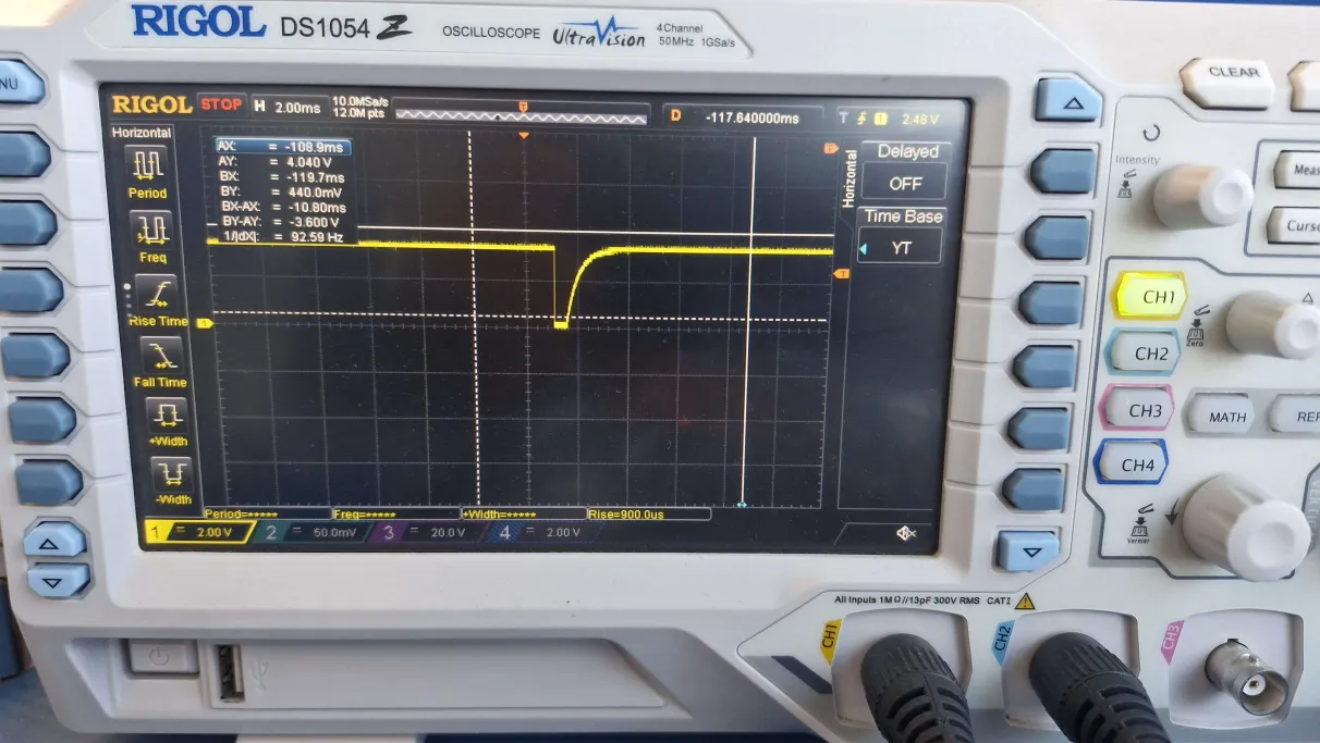
  • I can show you what the signals look like. The RDY pin going low is something that gives the signal to the sensor (I am afraid I cannot tell you the name) that the chip needs to process the data. It mimics human touch and the chip thinks "Hey I need to process the data now".

    It is not very close the MCU. 

    Also, the problem I have described in this comment appears to have "gone" when I call the "UCS_getSMCLK()" in the main while loop. I am doing this test at 6MHz (SMCLK). 

  • This is a bit puzzling. Thinks to consider:

    1) I'm pretty sure that to run at 24MHz you need to set PMMVCORE=3, but I don't see that here. You might try adding:

    > PMM_setVCore(PMMCOREV_3);

    2) I had thought that getSMCLK treated everything as read-only, but there is one case -- if XT2OFFG is set -- that it will clear that and OFIFG. This is only half-a-theory since there's no other evidence that XT2 is wobbling.

    3) It might be informative to watch SMCLK (maybe via a timer output pin?) to see if XT2 is indeed wobbling.

    4) As a "backstop", set a breakpoint at the 2nd line of main(), to see if you're getting (unnoticed) resets.

    5) Are you fairly certain your I2C clock divider (BR1/0) is correct? It seems possible that trouble with the I2C could lead to erratic RDY behavior from the sensor.

  • Thanks a lot for all the efforts, Bruce. The issue is solved, let me be as descriptive as possible.

    The RDY pin on the sensor side was Pulled-up to the VCC using a 4.7K ohm resistor and a 100nF capacitor. The RDY pin is "open-drain active low implementation". The charging time of this RC Ckt was around 470uS. For the MCU to detect it as HIGH, the voltage needs to be at least 1.5V and max 2.10V. Let's say it detects at 2.10V.

    Now the charging time or the time that we need to wait for the pin to stabilize and be read as HIGH was not met. The input is not Schmitt Trigger in this case it is an Input pin and not an interrupt on change pin.

    So when I was reading the clock frequencies before checking the state of the RDY input pin, it was getting the time to stabilize before it tells the MCU - "hey, I am HIGH now." I replaced the "reading clock frequencies" part with the some delay and it worked. So I experimented with different values, and 100us delay seems perfect. So that explains why "reading clock frequencies" was working. It was actually buying some time for the pin to stabilize and report it's voltage to the MCU. When I had removed or commented the "reading clock frequencies" code, the RDY pin was not getting enough time and it was reporting any voltage, hence the floating behavior. 

    Another thing: adding an internal software pull up worked. The reason was the internal pull up, which is typically 35K ohm and it is added in parallel, the effective resistance was 3.8k ohm. So we reduced the resistance and the charging time improved. 

    So in the current code, I have enabled the software internal pull-up and also added a 100us delay before I read the state of the pin. 

**Attention** This is a public forum