This thread has been locked.

If you have a related question, please click the "Ask a related question" button in the top right corner. The newly created question will be automatically linked to this question.

MSP430F5529: Use I2C Module to read data - after set MCLK as 32MHz

Part Number: MSP430F5529
Other Parts Discussed in Thread: TPS544C20, LM5066I

Tool/software:

Hi,

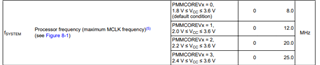
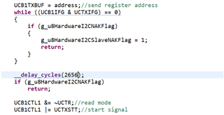
When I use I2C module of MSP430F5529, some problems happened. I use the following code to send one read-byte signal. (current MCLK is 32MHz)

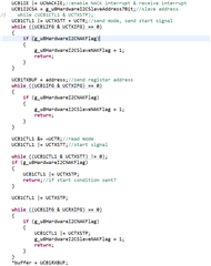
The interrupt code is as following 

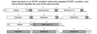
After I2C module initiation, I enable NACK interrupt, and start to transmit read-byte signal. The signal I want to send is as following 

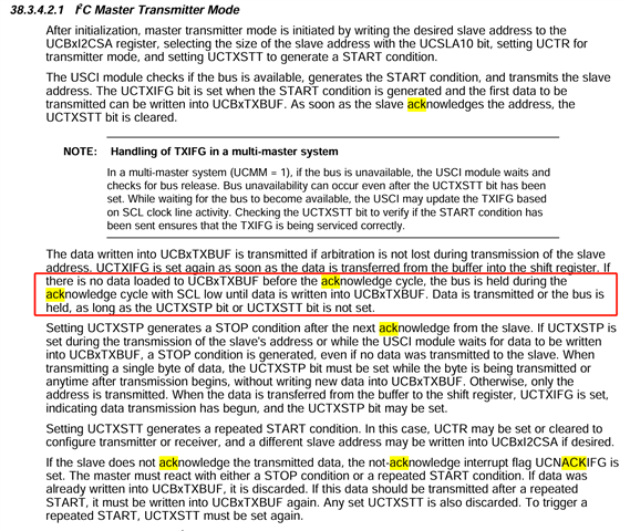
When I test if receive NAK reply before repeat start signal, something I does not expect happened, for example

I want to send stop signal when I receive NAK signal, in the above example, I want to send stop signal after receive 0x00[NAK], and the following read signal will not send any more, just like following

Is there any problem with my code? How can I change my code to realize the expected function and fix this problem?

Best Regard,

ZJY

  • I'm pretty sure the F5529 is limited to 25MHz [Ref datasheet (SLAS590P) Sec 8.3 "Fsystem"] Do you see this behavior with MCLK=25MHz?

    What is your slave device? Is there a reason it might reject a register number of 0x00?

  • Hi Bruce, 

    Thank you for your reply.

    1. About the MCLK, I have test the MCLK output it is really the value I set (32MHz), according to current test, MCLK can over the spec. Because of other function requirement in this system, the MCLK can not be decreased to 25MHz. (You think this problem may because of MCLK is too high?)

    2. About the slave device, I test this process with one PMBus device, this device not support the command PAGE which command code is 0x00, so it reply with NAK

    Best Regard,

    ZJY

  • TI [wisely, I think] doesn't specify what happens if you operate a device outside its specifications.

    That said: Based on what you've described, this I2C behavior does not seem unexpected. I'm not sure what your question is.

  • Hi Bruce,

    From my perspective, I need I2C stop immediately when I receive the NAK reply, just as what I wrote in interrupt code. That is to say, the main code should return and will not send read-start signal any more.

    But exactly, the I2C flow is like following, even I received NAK reply, it keeps send read-start signal which is nor my expected behavior.

    I want to make sure why this happened. Is there any thing wrong with my main code, or may because of the high MCLK?

    By the way, when I try to run the code step by step. I found that the time MCU turn to run interrupt code is later than "UCB1CTL1 |= UCTXSTT;". Is that because of the MCLK is too high, and makes the code operation faster than the hardware response?

    About MCLK, I still fill confused. If I change the MCLK source to extern crystal and use crystal with higher frequency, based on the internal PLL, it is possible to make the MCLK very high (over 25MHz). But spec said the MCLK should be lower than 25MHz, where does this limitation come from? Functional Module (like Timer/ ADC and so on) response limitation (such as hardware set interrupt flag need time or something else)?

    Best Regards,

    ZJY

  • By the way, I have tested, this problem still happened when MCLK is dropped to 8MHz

  • Hi ZJY,

    We limit the fsystem (MCLK) as 25MHz in the datasheet:

    Also limit the I2C clock the same as MCLK:

    The limitiation comes from the microcontroller design. And we do not guarantee the spec out of the range.

    I want to make sure why this happened. Is there any thing wrong with my main code, or may because of the high MCLK?

    What I suspect is that, the NAK reply from salve is late than you process the NAK check.

    If you are working with following data transfer, the TXBUF will be discarded where there is a NAK occurs.

    While if you are working with next re-start signal, there looks like no hardware mechanism to discard it. So, I suggest you add some dealy before next re-start signal and see whether it could work.

    B.R.

    Sal

  • [What Sal said, only more specific:]

    If you look at the flow chart in User Guide (SLAU208Q) Fig 38-12 (top line), the second time TXIFG is set to 1 occurs before the first data byte has been sent, and thus long before a NACK (for that byte) can be seen. This is because TXBUF is a holding register, and becomes empty when its contents are transferred to the shift register, not when the shift-out is complete.

    Inserting a delay to allow the shift-out of the data byte (as Sal suggests) would work, though it might be difficult to calibrate.

    Does your slave Require a Repeated Start [most don't]? I suspect if you explicitly Stop between the Write and Read transactions, any NACKIFG will be triggered before  the Stop is complete.

    [Edit: Fixed typo]

  • Hi Sal, 

    Thank you for your reply. I try to add some delay before next re-start. It needs a really long delay time (longer than the I2C frequency). Although, the delay fixed the wrong case, but this results in unexpected phenomenon in normal case (the delay time is added between No8 SCL and No9 SCL), as following

    The code delay I add is like following

    From my perspective, adding delay time may be not a good idea!

    Best Regard,

    ZJY

  • Hi Bruce,

    Thank you for your reply, it is very specific.

    As I want to use the I2C module to realize PMBus communication. However, in the PMBus spec, it said that there should not be STOP signal before Re-Start signal. So I could not add STOP to trigger the NACKIFG.

    Best Regards,

    ZJY

  • The USCI gives no explicit indicator that a byte has been shifted out (and has been ACK-ed).

    You might get some use out of UCSCLLOW [Ref UG Sec 38.3.5.1], since the clock will be stretched once the shift-out is done (if UCTXIFG=1). Since all that bit indicates is that SCL is low, you'll still need to calibrate (guess) what a "long time" is, but that would be based on the I2C bit-time, and thus much shorter (and slightly less arbitrary).

  • I don't have the PMBus spec (I'm not an Adopter), but I wonder(?) if sending ByteCount=0 in the Write transfer is legal. If so, you could send that as the second byte (fulfills second TXIFG=1) then watch for the third TXIFG=1. If you get an ACK on the first byte, it will send the 0x00 byte but that would be benign.

  • Hi Bruce,

    I knew what you mean, the above problem happens when the last byte before re-start receive NAK reply. The way you mean may be like to send one more byte to trigger NAKIFG. Maybe it is not a good idea.

    Best Regards,

    ZJY

  • Hi Bruce,

    About the delay time setting, I have tested.

    As the MCLK is 32MHz, and the current I2C frequency is 100kHz, so I add 83us delay (9 SCL) to make sure the NAK reply was received. 

    But in normal case, there still add about 17us delay (with another 7us delay when compared with I2C spec) between No8 and No9 SCL as following.

    I also tried to set delay time much shorter (82us), the NAK reply will not be checked and go to send re-start signal. So the time delay for this board is 83us (this delay time is also not a good setting because of additional 7us delay between No8 and No9 SCL) and there is no tolerance

    By the way, if I change another board, the delay time may be changed to another value, because of the deviation of MCLK.

    Is there any other way to solve this problem?

    Best Regards,

    ZJY

  • I've run out of ideas. You can't check whether a byte has been ACK-ed until it has been shifted out, and I don't know of any explicit indicator that this has happened. So all I can think of is (a) a sync point (a Stop or another Tx byte) or (b) a time delay (fixed or based on UCSCLLOW).

    UCBBUSY is defined to be =1 from Start to Stop [Ref UG Sec 38.3.2], so that doesn't help. 

    -------------

    The PMBus library from TI (here) doesn't seem to do anything special to deal with a NACK from an invalid command, so maybe it would run into the same thing. I did notice:

    1) None of the examples (for the TPS544C20) intentionally uses an invalid command.

    2) All of the examples enable PEC; I wonder if the PEC byte ends up serving the same (sync point) purpose as the ByteCount=0 byte I was suggesting.

  • Hi Bruce,

    About PEC byte, I have test with LM5066i (TI's PMBus device which supports PEC check). When communicating with LM5066i, I2C master can choose to send PEC byte or not (during write process). It is not one necessary byte. Meanwhile, during the reading process (like read process) the PEC byte is sent by slave not master (after re-start read signal), at the end of readback data, so it can not be used as the sync point.

    Best Regards,

    ZJY

  • I'll point out here that the request you showed (with the invalid command) did in fact fail. I suppose it was because the transaction was broken into two by the Stop, but maybe it had to do with the initial NACK. But I guess in that case there's no way to distinguish (for the caller) between "invalid command" and the more generic "request failed". Maybe this was considered to be sufficient for the TI library design .

    I'm not in a position to change how the MSP430 I2C unit works, so if none of the suggested accommodations -- sync, delay, or ignore the question -- fits your project requirements, you may need to consider a different MCU. The MSPM0 (e.g.) I2C unit works on a transfer/transaction, rather than a per-byte basis, and it distinguishes between a SLA-byte NACK and a data-byte NACK, so maybe (I haven't tried your test case) it would fit your needs better.

    Or maybe someone else on the Forum has another suggestion?

  • Hi ZJY,

    I also tried to set delay time much shorter (82us), the NAK reply will not be checked and go to send re-start signal. So the time delay for this board is 83us (this delay time is also not a good setting because of additional 7us delay between No8 and No9 SCL) and there is no tolerance

    Yes, it is expected according to the UG said:

    I have no additional idea right now, while I have found that we support PMBUS for msp430, maybe you can take a look at it and  see how it achieve the repeat start signal processing: MSP-PMBUS Driver or library | TI.com

    B.R.

    Sal

**Attention** This is a public forum