This thread has been locked.

If you have a related question, please click the "Ask a related question" button in the top right corner. The newly created question will be automatically linked to this question.

LP-MSPM0G3519: MCLK clock configuration gives error

Part Number: LP-MSPM0G3519
Other Parts Discussed in Thread: MSPM0G3519, SYSCONFIG

Tool/software:

Hello TI Team,

I faced problem during MCU clock configuration. When I try to select clock source for MCLK as HSCLK, we can see in below image, and I flash code on MCU, MCU does not get running and going into unpredictable state. Even I cannot flash it in similar way as I used to flash earlier. Is there any specific setting I need to look into it.?

As per technical reference manual, SYSPLLCLK0 or SYSPLLCLK2X as the source of HSCLK before setting HSCLK as the clock source of MCLK. And is this done through Mcu_HSCLKSrc selection?

.
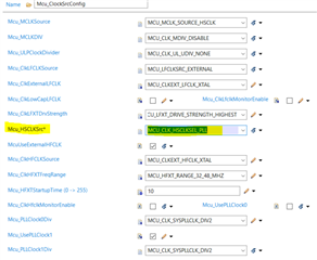
I am selecting Mcu_HSCLKSrc as below:

Is there any other parameter do I need to check?

Thanks & Regards,

Rohidas Khurange

  • Hi Rohidas,

    As per technical reference manual, SYSPLLCLK0 or SYSPLLCLK2X as the source of HSCLK before setting HSCLK as the clock source of MCLK. And is this done through Mcu_HSCLKSrc selection?

    No, it is configured by Mcu_PLLClock2HSCLK.

    As you does not share the whole clock configuration. I will recommend you to follow the MSPM0 MCAL sample Mcu configuration about clock, MCLK is also configured from SYSPLL. You could test with below configuration.

    Regards,

    Pengfei

  • Hello Pengfei,

    Currently, I am using the MSPM0 MCAL sample MCU configuration and making some changes as per the requirements.

    I observed that the SYSTEM OSC is used as the source for the PLL, and the entire clock system is working on SYS_OSC. On the CLK_OUT pin, I observed different clocks:

    • ULPCLK: 32MHz
    • MFPCLK: No clock

    I want to change the PLL clock source from SYSOSC to HFCLK.

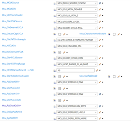
    Below is the full configuration.

  • Hi Rohidas,

    Are you using our MSPM0G3519 launchpad for test or your own board. Just want to make sure the oscillator works well.

    Best Regards,

    Pengfei

  • Hello Pengfei,

    Yes, I am using MSPM0G3519 launchpad for test.

  • Hello Pengfei,

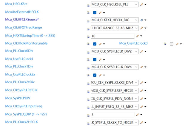
    Below is the updated configuration. I am trying to use CLK2X from SYSPLL with below configuration. When I select MCU_CLK_HSCLKSEL_PLL in highlighted sections in below image, mcu is going into unpredictable state. And if keep MCU_CLK_HSCLKSEL_HFCLK in highlighted section, mcu is running and I can observe 40MHz on ULPCLK. I want to achive 80 MHz on MCLK, please guide me with below configuration.

    Thanks & regards,

    Rohidas Khurange

  • Hi Rohidas Khurange

    When you select MCU_CLK_HSCLKSEL_HFCLK for Mcu_HSCLKSrc, you are directly using external XTAL oscillator(40MHz) as MCLK and ULPCLK source, so 40MHz could be observed on ULPCLK. For achieving 80MHz MCLK, you need to select MCU_CLK_HSCLKSEL_PLL as Mcu_HSCLKSrc to use syspll module. And there are some changes you could make for configuring syspll:

    1. Mcu_SysPLLPDIV : MCU_CLK_SYSPLL_PDIV_NONE

    2. Mcu_PLLClock2xDiv : MCU_CLK_SYSPLLCLKX2_DIV4

    3. Mcu_ULPClockDivider: MCU_CLK_UL_UDIV_2

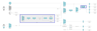
    Actually you could refer the clock tree of sysconfig to help about what these parameters mean:

    Best Regards,

    Pengfei

  • Hello Pengfei,

    Thanks for the inputs. I tried with your suggested changes, but I could not be able to achieve MCLK to 80MHz. Is there any difference while doing the configuration though EB Tresos? I am using EB Tresos for MCAL configuration.

    Also, I tried with different values in the PDIV and QDIV for PLL, but sometimes device is going to unpredictable state, and it's taking lot of time to troubleshoot and recover the board from those states.

    I am checking ULPCLK on CLK_OUT pin and based on ULPCLK, I am assuming MCLK = ULPCLK x 2, as UDIV is MCU_CLK_UL_UDIV_2. Is there any other way to identify/ to check MCLK?

    Thanks & Regards,

    Rohidas

  • Hi Rohidas,

    Sorry I missed one point:

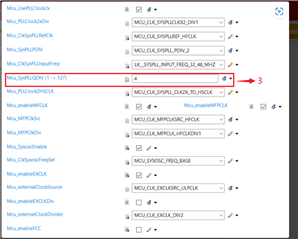
    • The Mcu_SysPLLQDIV should be set as three. When it is set as three, it is actually 4 times of the source clock.

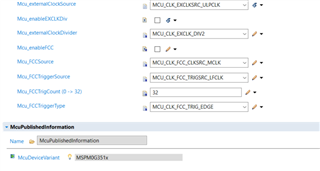
    I attached the correct configurator for 80MHz MCLK sourced from external 40MHz oscillator. You will observe 20MHz of external clock output from clock_out pin (default from PA31, it depends on your Port setting), which is 2 divider from ULPCLK. (ULPCLK is 1/2 of MCLK, that is 40MHz, and the clock output is 1/2 of ULPCLK determined by Mcu_externalClockDivider).

    https://e2e.ti.com/cfs-file/__key/communityserver-discussions-components-files/166/Mcu.xdm

    Best Regards,

    Pengfei

  • Hello Pengfei,

    Thanks for the inputs. I was able to achieve 80MHz PLL output and able to get it at MCLK.

    Now, I see different behavior. When I flash MSPM0G3519 Launchpad through CCS, clock and board is running properly. 

    But if try to reflash the code with other debugger (Trace32 - Lauterbach in our case) on same board it is getting into hard fault. What could be the reason?

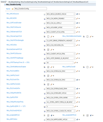
    Clock Configuration:

    HardFault error stackframe:

    Thanks & Regards,

    Rohidas 

  • Hi Rohidas,

    A hard fault could be caused by access incorrect memory, such as program jump to a wrong address, or access for a variable not 32bit aligned.

    Could you see where does the hard fault handler entered from? I think you could check the stack memory to see the PC value before the hard fault for debugging.

    Best Regards,

    Pengfei

  • Hello Pengfei,

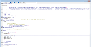
    Hard fault is occurring while executing Mcu_SyspllSetting() as we can see in below stack frame screenshot:

  • Hi Rohidas,

    I checked the clock configuration and I think it looks fine.

    What if you debug this project with XDS110 for the second time, will this issue still happen?

    Or only when you are debug with Trace32 debugger, the issue happens?

    Best Regards,

    Pengfei

  • Hi Pengfei,

    If I debug/flash project with XDS110 for many times and I didn't find any issue. 

    But with same project, when I am trying debug/flash with Trace32 debugger, the issue occurs.

    Thanks!

    Rohidas

  • Hi Rohidas,

    Got it. Actually the showing sentence is a general register configuration code for syspll. And this issue is Trace32 debugger related.

    Sorry I have no experience of this debugger from my side, is it acceptable for you to use XDS110 instead for development and debug?

    Best Regards,

    Pengfei

  • Hello Pengfei,

    I didn't understand the issue. Could you please elaborate it?

    What does CCS/XDS110, so that the issue is not observed with XDS110?

    Thanks!

    Rohidas

  • Hi Rohidas,

    You could take below steps for some debug of this issue:

    1. Firstly, please check whether debug or flash by Trace32 causes hard fault, or both of them.
    2. When debug the same project by XDS110 and Trace32, stop before program is running. Read and export all flash data, to compare whether there is any difference between using these two debugger, especially the Mcu_SyspllSetting() function place.
    3. When using Trace32 and debug the project, stop at the hard fault handler, and check below registers:
      1. SP (Stack Pointer): Go to the SRAM address pointed by SP.
      2. Check the PC (Program Counter) value before the hard fault is generated. The CPU will store the core register to stack before it jump to a interrupt handler. And the core register storage order could be found at Exception entry of Cortex-M0+ Devices Generic User Guide
      3. View disassembly code and check what is the disassembly instruction according to the PC value of step b.

    Best Regards,

    Pengfei

**Attention** This is a public forum