This thread has been locked.

If you have a related question, please click the "Ask a related question" button in the top right corner. The newly created question will be automatically linked to this question.

CC2500 2.4GHz RF Transceiver

Other Parts Discussed in Thread: MSP430F2274, CC2500

Hello everyone,

I have some problem using a MSP430f2274 with a RF Transceiver CC2500.

The situation is described below:
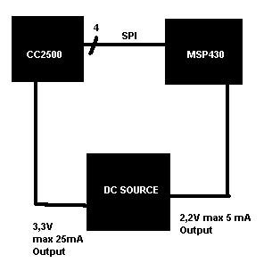
Now the problem is.

If I try to source the CC2500, the DC-Output fall down to ca. 1V. I suppose the CC2500 exceeds 25mA for a few ms on the first start-up. In the Datasheet http://www.ti.com/lit/ds/symlink/cc2500.pdf page 20 is described that the idle mode current consumption is typ. 1.5mA.


The second problem is: If the SPI connection (SI,SO,CLK,Cs) to the CC2500 is connected, the 2,2V DC-Output fall down to 1.8V even though the 3,3V DC-Output is not connected on the CC2500. It seems the CC2500 take current from the ports. I figured this out by disconnecting  the SPI from the CC2500 to the MSP430 and the DC-Output is not falling.


I tryed to start the CC2500 and MSP430 with an other source with more output power and after they started I switched the source to the DC-Source described above.
The result is that it works fine with the source but I need start-up aid. My big problem is, I have only the possibility to use the DC-Source described above.

How can I solve this problem?


Best Regards

Patrick


  • Hello Patrick,

    Have you considered to use a level shifter on SPI interface. The SPI output of CC2500 (0 .. 3.3V) may trigger the input protection diode of MSP430 (2.2V + 0.7V = 2.9V). Or use same voltage rail for both parts.

    You can buffer the inrush drop by a large capacitor or even supercap.

    Regards

    Guenther

  • Maybe some series resistors in the SPI paths are enough to just limit the current flowing through the clamp diodes. They are specified for 2mA at 0.3V if I remember correctly. A resistor of 1kOhm should already be enough to prevent excessive current.

    But I guess the 2.2V are not detected as logic 1 as it's specified in the data sheet from VDD-0.7 to VDD, so it's 2.6 - 3.3 volts in this case.

    So for the MSP outputs there should probably be some sort of level shifter used. For the inputs the current limiting resistor might be enough.

  • Why do you use a dual DC source for CC2500 and MSP?

    If you already need 3,3V for the CC2500, you can use the same for the MSP too. Which saves you the hassle with the logic voltage levels between the two (which at the end comes to additional components for the level shifting).

    The higher power consumption of the MSP at the higher voltage si compensated by not needign a voltag elevel shifter and by a higher performance of the DC source, which only needs to generate one voltage then.

  • Thank you for the answers!

    Jens-Michael Gross said:

    Why do you use a dual DC source for CC2500 and MSP?

    I use a dual DC source because of  a special application and development. Of course you be right to use the same voltage. I changed both to 2,2 Volt.

    Regards Patrick

**Attention** This is a public forum