This thread has been locked.

If you have a related question, please click the "Ask a related question" button in the top right corner. The newly created question will be automatically linked to this question.

TIDM-02003: R14 role in the PCB schematics of TIDM-02003

Part Number: TIDM-02003


Tool/software:

Hi all,

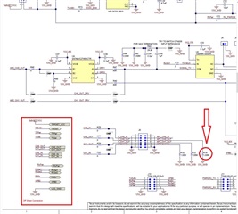
I was asked by a customer of mine what is the role of R14 on PCB schematics. Customer did not place this resistor on the PCB because the channel is driven, so they have assumed that it would have no impact. 

Is it true?

So far I've only found a post in which it was only mentioned that R14 was necessary int the design without any explanation as to why.

Could you help me with this question?

BR,

Adam

  • R14 is on the attached picture.

  • Hi,

    R14 is necessary for the meter performance. I do not know exactly why but I would assume that it could relate to impedance matching on CH0_OUT and CH1_OUT pin. 

    We do not recommend to remove R14 on gas meter application. 

    Best regards,

    Cash Hao

  • Hi Cash,

    this is the reply from the customer:

    However, it would be much better to have a proper technical justification, since our current test PCBs do not have the option to populate the 1 MΩ resistor. With a better understanding of its role, I could better evaluate how critical it really is in our application.

    As far as I know, the gas sensing firmware doesn't even utilize the CH1_OUT channel. It would be important to know whether this resistor is required due to something like an initialization-time measurement (which seems unlikely), or if the CH0_OUT pin goes into high impedance mode between the transmit and receive phases—potentially causing the buffer behind it to unintentionally power the transducer.

    In our case, this shouldn’t be an issue, because the transducer is directly driven by the MSP.

    So in short, this customer would really like to receive a bit more of a technical justification as to why this 1M resistor should be included on theirs PCB. 

    BR,

    Adam

  • Hi Adam,

    I did some research and some says that the resistance of a 1Mohm resistor is usually matched to the input impedance of signal source, thereby reducing reflection and distortion of the signal during transmission. This matching helps maintain the amplitude and timing of the signal and avoids signal distortion or increased delay caused by impedance mismatch.

    The 1Mohm resistor can be used as a load in the signal transmission path to limit the amplitude of the signal, thereby preventing the signal from being distorted due to overload during transmission.

    In electrostatically sensitive environments, 1Mohm resistors can be used as part of the ground path to discharge static charge and prevent electrostatic discharge (ESD) from damaging the circuit.

    Best regards,

    Cash Hao

**Attention** This is a public forum