This thread has been locked.

If you have a related question, please click the "Ask a related question" button in the top right corner. The newly created question will be automatically linked to this question.

MSP430FR2476: PWM Compare Value update skips one cycle

Part Number: MSP430FR2476

Tool/software:

Hi,
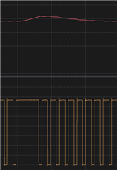
I'm working with the MSP430FR4276 microcontroller and encountering an issue while generating a PWM signal using Timer_A3. The PWM duty cycle needs to be adjustable at any time by my PI controller. However, I'm facing a problem (as shown in the attached image) that I believe is related to the timing of when I update CCR1.

It seems that if I update CCR1 at the wrong moment, the compare event between CCR1 and CCR0 doesn't occur until the timer reaches its maximum value. As a result, the new duty cycle only takes effect in the next cycle.

The challenge is that I don't want to stop the timer using the MC bits, nor do I want to use interrupts (ISRs). According to the datasheet, shadow registers are used for this purpose and should be automatically handled by Timer_A_initCompareMode(). Therefore, I expected that simply calling: 

Timer_A_setCompareValue(TA3_BASE, TIMER_A_CAPTURECOMPARE_REGISTER_1, newDutyCycle);

void MY_TIMER_init(void)
{
  // Set up Timer_A3 in Up Mode
  Timer_A_initUpModeParam upModeParams = {0};
  upModeParams.clockSource = TIMER_A_CLOCKSOURCE_SMCLK;
  upModeParams.clockSourceDivider = TIMER_A_CLOCKSOURCE_DIVIDER_1;
  upModeParams.timerPeriod = 0xFFF;
  upModeParams.timerInterruptEnable_TAIE = TIMER_A_TAIE_INTERRUPT_DISABLE;
  upModeParams.captureCompareInterruptEnable_CCR0_CCIE = TIMER_A_CCIE_CCR0_INTERRUPT_DISABLE;
  upModeParams.timerClear = TIMER_A_DO_CLEAR;
  upModeParams.startTimer = false;


  Timer_A_initUpMode(TA3_BASE, &upModeParams);


  // Configure CCR1 for PWM output
  Timer_A_initCompareModeParam compareParams = {0};
  compareParams.compareRegister = TIMER_A_CAPTURECOMPARE_REGISTER_1;
  compareParams.compareInterruptEnable = TIMER_A_CAPTURECOMPARE_INTERRUPT_DISABLE;
  compareParams.compareOutputMode = TIMER_A_OUTPUTMODE_RESET_SET;
  compareParams.compareValue = 0x7FF;


  Timer_A_initCompareMode(TA3_BASE, &compareParams);
  Timer_A_startCounter(TA3_BASE, TIMER_A_UP_MODE);
}

  • Hello Strahinja,

    The shadow register is used for "updating duty cycle or load value when current PWM period ends". Using shadow register won't make PWM change immediately, it will change PWM after current PWM period ends. And in fact, I remember that our technical reference manual doesn't recommend to change PWM duty cycle or load value when current PWM has not ended. And I think maybe you need to double check whether TIMER_A has shadow register in  MSP430FR2476

    More information about the timer register usage method, you can try to refer to the technical reference manual. If you don't use shadow register, I think the duty cycle or load value will be changed immediately after you change them in your code.

    Best Regards,

    Janz Bai

  • Janz is correct that TimerA doesn't have shadow registers. TimerB does in theory, but they don't actually work [Ref Errata (SLAZ726B) item TB25], so there are (in effect) no shadow registers anywhere.

    Updating a CCR requires some strategy; it helps if there's some known pattern to the CCR value settings. Updating at a CCR0 (vs CCR1) interrupt is often the better choice. You don't have to stop the timer to change a CCR.

  • As the guide says, changing CCRx while the timer is running can result in unexpected behaviour.

    For example, the current value in CCR1 is greater than the timer count but the new value is less. Writing the new value to CCR1 will result in CCR1 not being matched this cycle. To avoid a skipped cycle you will have to do something to avoid that.

  • I looked into it, and yes — the shadow registers are indeed for TimerB. Following Bruce McKenney’s post, it appears they don’t function properly, so an alternative strategy is needed.

    I changed the timer to Up/Down mode to take advantage of the Toggle/Reset Output Mode. Since the timer checks the compare value twice per cycle, if it misses the update on the first compare, it can still catch it on the second. This approach worked well without the PI control.

    However, once I added the PI controller, some undesired behavior appeared.

    The best solution seems to be using the Interrupt Service Routine (ISR). To ensure smooth operation, the interrupt should be configured to prevent nested interrupts, which could interfere with updating the compare register. Additionally, the interrupt priority should be carefully checked and set to avoid conflicts.

  • Hello Lukic,

    I agree with Bruce's comments. Updating at a CCR0 (vs CCR1) interrupt is often the better choice. And maybe you can think about using other device having Timer A if you need and want. For example, MSPM0 family

    Best Regards,

    Janz Bai

  • As David described, the hazard has to do with the relationships between the old/new values and the current counter value, and between each other; in theory, you could compute these but that introduces races. Changing the CCR1 value at the CCR0 interrupt at least gives you a predictable relationship, and the hazard appears only if CCR1 is very small.

    ISRs are entered with interrupts disabled (GIE=0) so nested interrupts won't happen unless you do something special (I don't recommend it). Priority is mainly a concern if you have large ISRs (also not recommended).

**Attention** This is a public forum