This thread has been locked.

If you have a related question, please click the "Ask a related question" button in the top right corner. The newly created question will be automatically linked to this question.

MSP430FR6047: Device may enter lockup state during transition from AM to LPM2/3/4 stated in errata of MSP430FR6047.

Part Number: MSP430FR6047

Tool/software:

In my application, the main code starts and then enters LPM3 mode. The application exits LPM3 under the following conditions:

  1. An interrupt occurs every 15.625 ms, and its ISR is served without exiting LPM3 mode.

  2. Every 125 ms, the system exits LPM3 using the instruction LPM4_EXIT, serves the super loop (while(1U)) once, and then returns to LPM3 mode. This cycle repeats every 125 ms.

  3. During both LPM3 and active modes, the UART remains active and operates using SMCLK, which runs at the same frequency as MCLK (8 MHz).

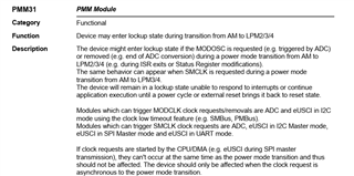
Given the conditions described above, does this scenario fall under the device erratum stating:

"Device may enter lockup state during transition from AM to LPM2/3/4. When SMCLK is requested during a power mode transition from AM to LPM3/4."

If it does then how to exit this lockup state.

  • Hi,

    Are you using UART to wake MCU up from LMP to AM? If not, I would say your code is fine. 

    Best regards,

    Cash Hao

  • Hi Cash,

    Thank you for your response.

    In our case, UART is always active, and we are using DMA to transfer any received data into a buffer automatically.

    My concern is related to the device errata, which states that during a transition from Active Mode (AM) to LPM3 (e.g. during ISR exits or Status Register modifications), if any peripheral (other than the CPU) requests SMCLK, the CPU may enter a lockup state.

    We are interpreting this erratum as follows:

    • We have a timer interrupt that triggers every 15.625 ms.

    • In every 125 ms (i.e., on every 8th interrupt), we exit LPM3 and serve the while(1) loop once before returning to LPM3.

    • Therefore, during the return to LPM3, a transition from AM to LPM3 occurs.

    • Since our UART is always active, if any data is received on UART during this exact transition, it could potentially request SMCLK — thus satisfying the conditions of the erratum.

    Are we correct in this interpretation? if not what is correct interpretation of this erratum statement.

    Below is the snap of Erratum i am asking about. and also in one of it's work-around it is stating to wake-up Cpu before uart byte is recieved.  

    Waiting for a fruitful response.

  • In our case, UART is always active,

    If the UART is really active, then it isn't a problem. But if the UART is ever idle, as in not actively transmitting or receiving data, it could be a problem.

    On the other hand, if the UART really is that active then you aren't really in LPM3. With SMCLK requested you get LPM1. So you could just use LPM1 anyway and remove all doubt.

  • Hi,

    Agreed with David's comment. If the UART is always active then you will not entering LPM3 since the SMCLK is been used by UART. And for your application, like I said do not use UART to wake up the MCU from LPM3 it would help you avoid this bug. Only use timer to wake up the MCU, when the MCU goes back to AM, you can send and receive data through UART. If you want to receive data in LPM3 mode. Configure RX pin as GPIO input and use fall edge to wake up the MCU in LPM3 mode. The first 8-bit message will be used as dummy message for wake up device. 

    Best regards,

    Cash Hao

  • Thanks for the reply.

    Sorry for the confusion due to this line i.e.

    "In our case, UART is always active,"

    By this, I mean that my UART Initialization has been done and it is configured for reception and transmission. After doing this, i goes into LPM3 mode and then i am ready to receive any byte in LPM3 mode. Does this condition make my application fall into the stated erratum i.e. 

    "Device may enter lockup state during transition from AM to LPM2/3/4. When SMCLK is requested during a power mode transition from AM to LPM3/4."

    If i want to receive a byte in LPM3 mode without falling into the above stated erratum, how can i achieve this.

    In continuation to this i have one more query:

    If we run our UART on ACLK(i.e 32768 Hz), then this issue should not occur as ACLK is active in LPM3 mode.

    But in user-manual generating Baud Rate using ACLK, the TX and RX error percentage would be increased in comparison of using SMCLK(8 Mhz).

    As shown in the above picture, RX and TX errors percentage is too high for ACLK.

    What is the exact meaning of these errors? Are they related to bit timing — for example, during transmission, does a TX error of +16.02% or -17.19% mean that each bit is off by that percentage? , and in the case of RX this error is 37.3 and -23.24 percent ,what does this mean.

    Our product has Optical LED based communication, what effect will be of these errors in the real time or field case scenarios.

  • The problem described in the errata can occur in your case. Why? Because a character could arrive causing the UART to request SMCLK at the same time as a transition to LPM3. Such as when your timer ISR is exiting.

    Using ACLK is a workaround described in the errata so that would work.

    The timing errors are how much the sampling at the center of each bit time deviates from the actual center of the bit. If this gets too close to the edge of a bit time, errors occur. Also dependent on the accuracy of the device on the other end. The guide has a detailed description of how to calculate timing errors.

    Note that using SMCLK and LPM3 also has bit timing errors. It takes time for the clock to start and this skews the bit times since they are all referenced to the falling edge of the start bit. Less of a problem at lower bit rates.

  • As an additional comment, like I said in the former post, Configure RX pin as GPIO input and use fall edge to wake up the MCU in LPM3 mode. Use the GPIO interrupt to wake up MCU form LPM mode since the GPIO port will not request SMCLK. It can help you avoid this issue. 

    Best regards,

    Cash Hao

  • Hi Cash & David,

    Thanks for your previous response.

    We’d like to clarify one more point regarding UART operation. Currently, we are interfacing three UART peripherals with three external devices, all operating at 9600 baud using SMCLK as BRCLK and operating in LPM3. However, due to the erratum associated with SMCLK-based UART operation, we are considering switching to using ACLK (32.768 kHz) for BRCLK to enable low-power operation.

    We reviewed the datasheet and observed that both RX and TX error percentages are relatively high at this baud rate when using ACLK.

    Question 1 :- Is it Ok to make use this configuration with this much high error?

    However, I have some doubts.

    If we use BRCLK = 32768 Hz and the desired baud rate is 9600, then the ideal number of BRCLK cycles per bit is:

    32768 / 9600 ≈ 3.41

    Using UCBRSx = 0x92 (modulation bit pattern: 10010010), as recommended in the user guide:

    TX Case (Transmitting at 9600):
    If we loosely estimate the transmit-side timing based on the modulation pattern, then for an 8-bit transmission, the number of BRCLKs used per bit follows the pattern:
    {4, 3, 3, 4, 3, 3, 4, 3} → Total = 27 BRCLKs

    The ideal total BRCLKs over 8 bits = 3.41 × 8 = 27.28

    So the TX error over a full byte ≈
    (27 − 27.28) / 27.28 × 100 = −1.02%

    This seems lower than the datasheet's stated TX error (~±17%).
    Is this calculation correct?

    RX Case (Receiving at 9600):
    The RX side comprises multiple errors:

    1. Synchronization Error:
      Sampling can be off by up to ±0.5 BRCLK.

    2. Per-bit Modulation Error:
      The modulation approximates to 3.41 BRCLK per bit using a pattern of 3s and 4s.

    For individual bits:

    • If 3 BRCLKs are used: error = −0.41 BRCLK (≈ −13%)

    • If 4 BRCLKs are used: error = +0.59 BRCLK (≈ +17%)

    Although this error accumulates per bit, the modulation pattern keeps the total drift limited. However, combining modulation-induced drift with the ±0.5 BRCLK sync error, the sampling point can drift up to 1 BRCLK in the worst case — which is ~33% of the bit period (for a 3 BRCLK bit).

    Hence, our key concern is:

    Question 2
    If interfaced devices with msp are also communicating with the same ACLK-based UART setup (i.e., both TX and RX suffer similar modulation/sync errors), could this lead to significant bit timing mismatch and communication failure? 


  • I have used the MSP430 UART at 9600bps using a 32768 LFXT with little trouble. The only trouble I have ever had was when communication was between two MSP430s and they were using different modulation patterns.  When the other end was, for example, a (real) PC serial port, there was no trouble.

    Your transmit calculation is wrong. What you care about is when the receiver samples the data. This will be, more or less, at the middle of each bit time as referenced to the falling edge of the start bit. The data sheet numbers reflect bit by bit calculations. 

    The error will be different from bit to bit. One being a little short and another being a little long. The modulation pattern tries to even this out so that the receiver will not be sampling too close to an edge.

**Attention** This is a public forum