This thread has been locked.

If you have a related question, please click the "Ask a related question" button in the top right corner. The newly created question will be automatically linked to this question.

MSP430FR6043: Sonic Not Ready UPSTATE_3 bit

Part Number: MSP430FR6043

Tool/software:

We have a custom board running the MSP430FR6043 based on the demo library. 

We have programmed hundreds of boards successfully, but we have a few that get hung up in the ultrasonic routine. We are trying to figure out what part of the hardware is not functioning correctly.

Several boards fail in the following code.  In this case the UPSTATE_3 bit of the UUPSCTL register never gets set, causing the watchdog timer to fire.  The actual failure occurs on this line :

             // Wait until USS module is in READY state

             while((UUPSCTL & UPSTATE_3) != UPSTATE_3);

What inputs to the TMS430FR6043 could cause this failure ?  Also where can we find a definition / description of the UPSTATE_3 bit ?  How else can we troubleshoot the hardware side of this?


Here is a large code snippet of the section.

 #pragma vector= USSLIB_HAL_TIMER_RXEN_CCR1_VECTOR

__interrupt void USSLIB_HAL_TIMER_RXEN_INT(void)

{


switch(__even_in_range(HARDWAREWREG16(USSSWLIB_HAL_RXEN_TIMER_BASE_ADDRESS

+ OFS_TAxIV),

                            TAIV__TAIFG))

     {

         case TAIV__NONE:   break;           // No interrupt

         case TAIV__TACCR1:                  // CCR1, Enables RXEN

             // Enable RxEN, RxEN will be turned Off after USS

acquisition

             USSSWLIB_HAL_AFE_RXEN_PORT |= (USSSWLIB_HAL_AFE_RXEN_PIN);

             // Disable Timer

             HARDWAREWREG16(USSSWLIB_HAL_RXEN_TIMER_BASE_ADDRESS +

OFS_TAxCTL) &= ~(MC_3 | TAIFG);

         break;

         case TAIV__TACCR2:           // CCR2, start ASQ, restart timer

to trigger RxEN

             // Wait until USS module is in READY state

             while((UUPSCTL & UPSTATE_3) != UPSTATE_3);

             // Stop timer

             HARDWAREWREG16(USSSWLIB_HAL_RXEN_TIMER_BASE_ADDRESS +

OFS_TAxCTL) &= ~(MC_3 | TAIFG);

             // Disable CCR2 interrupt

             HARDWAREWREG16(USSSWLIB_HAL_RXEN_TIMER_BASE_ADDRESS +

OFS_TAxCCTL2) = 0x00;

             // Enable CCR1 interrupt to enable RxEN

             HARDWAREWREG16(USSSWLIB_HAL_RXEN_TIMER_BASE_ADDRESS +

OFS_TAxCCTL1) = CCIE;

             // Restart timer

             HARDWAREWREG16(USSSWLIB_HAL_RXEN_TIMER_BASE_ADDRESS +

OFS_TAxCTL) |= ( TACLR | MC__CONTINOUS);

             // Trigger ASQ

             GENERIC_SAPH_ASQTRIG = ASQTRIG;

         break;

         case TAIV__TACCR3: break;           // reserved

         case TAIV__TACCR4: break;           // reserved

         case TAIV__TACCR5: break;           // reserved

         case TAIV__TACCR6: break;           // reserved

         case TAIV__TAIFG:  break;          // overflow

         default: break;

         }


}

  • Hi,

    For this kind of issue, I would check the USSXT first. Check if the crystal has the correct configuration. You can share what crystal you are using as the USSXT on your board. And the load cap values you are using. We can start on there for analyze. 

    Best regards,

    Cash Hao

  • Too clarify, this problem is isolated to a number of boards out of hundreds.  We are trying to isolate the problem so we can repair the boards and improve build quality.   We are confident the circuit and configuration are working. 

    Assistance in knowing what part of the circuit is appreciated.  We were wondering about the crystal.  Is there a way to test the crystal either with an Oscope or through the processor to see if it is functioning?

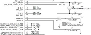
    See the following clip from the schematic. Part numbers and cap values are in the schematic.

    Visually the solder looks good on X3 and its caps/resistors. Using an ohm meter I made sure there was no conductivity where there shouldn’t be.  

  • Hi,

    Okay, you are using the same resonator on the EVM board. I would suggest to try with a higher load cap C5 and C6 to like 22pF to 30pF. 

    On a working board, you should be able to observe the crystal signal through an oscope. 

    Best regards,

    Cash Hao

  • We had to order new caps to test this out.  

    We are struggling trying to observe the crystal signal through an oscope.  Using a 10X probe and measuring on the output.  Any tips?

  • Hi,

    The USSXT is only oscillate when the USS module is working. You can use another channel to sample the CHx_OUT pin and configure it as a trigger. Then you should capture the crystal signal. 

    Best regards,

    Cash Hao

**Attention** This is a public forum