LP-MSPM0L2228: UART communication fail between two LP-MSPM0L2228 Evaluation Modules using 32.768 kHz crystal and identical UART settings

Part Number: LP-MSPM0L2228
Other Parts Discussed in Thread: MSP430FR6007, MSPM0L2228, MSP430FR6047

Tool/software:

Hi,

I am trying to send data between two LP-MSPM0L2228 boards using UART1 on both boards.

Our final use case is a setup where we need to operate in low power mode most of the time, which means that we cannot use HFCLK - hence LFCLK (LFXT 32.768 kHz) is chosen.

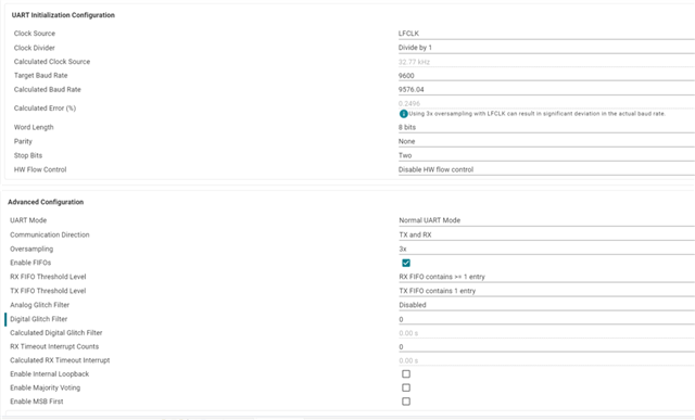
The UARTs must communicate at 9600 baud with 8 data bits, no parity and 2 stop bits to work with our existing setup, which consists of MSP430FR6007 devices along side non-TI devices all running their UARTs from a 32.768 kHz crystal.

When testing I use the "uart_echo_interrupts_standby" example and then I switch to LFXT and UART1 on pin PA8 + PA9. Furthermore, I have enabled CLKOUT on pin PA27 for the LFCLK.

For the RX project I have in addition a debug pin on PA25 indicating whenever the sample code detects an inconsistency in the received data.

If I set the following settings for the UARTs I get error free communication:

Source: MSPM0L2228 8N2 at 9576.04 baud -> Destination: MSPM0L2228 8N1 at 9709.04 baud  -> OK

Source: MSPM0L2228 8 <Stick One> 1 at 9576.04 baud -> Destination: MSPM0L2228 8N1 at 9709.04 baud  -> OK


If I set the following symmetric settings for both UARTs I do not get error free communication:

Source: MSPM0L2228 8N2 at 9576.04 baud -> Destination: MSPM0L2228 8N2 at 9576.04 baud  -> FAIL

Source: MSPM0L2228 8E1 at 9576.04 baud -> Destination: MSPM0L2228 8E1 at 9576.04  baud  -> FAIL

1) When I set up 2x MSPM0L2228 evaluation modules. One for TX and one for RX with the same settings (baud rate, parity and stop bits) then I do not get error free communication  - how come? Am I setting up my project wrong or is this behavior to be expected?

I also struggle getting our non-TI processor to receive an error free transmission from the MSPM0L2228. Though we previously have had the non-TI processors receiving flawlessly from MSP430FR6007.

2) Are there more parameters that I can adjust/tweak on the MSPM0L2228 in order to make the non-TI processor correctly receive a transmission from the MSPM0L2228. So far I have adjusted parity and stop bits along with baud rate (IBRD + FBRD)?

3) As far as I recall the MSP430FR6007 had a register where we could modify the bit modulation pattern. How exactly does the integer and fractional part of the MSPM0L2228 work and could that explain why we see our communication failing?

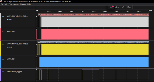
In the following I have provided 3 pictures showing what the logic analyzer has captured while two MSPM0L228 modules are communicating with each other.

Both boards are set up with 8 data bits, no parity and 2 stop bits – and a baud rate of 9576 (via syscfg).

The transmitting code sends a byte - increment it and sends it again.

The receiving code receives a byte and validates that it is one higher than the previous received byte - if not it toggles PA25 - regardless of if it was a match or not the byte is transmitted.


MCU1: MSPM0L2228 TX Src // TX from the source MSPM0L2228 board // (PA8_UART1-TX (Source MSPM02228 board))

MCU1: CLK // LFCLK from the source board // (PA27 (Source MSPM02228 board))

MCU3: MSPM0L2228 TX Dst // TX from the destination MSPM0L2228 board (the board echos out what it received from the source board) // (PA9_UART1-RX (Destination MSPM02228 board))

MCU3: CLK // LFCLK from the destination board // (PA27 (Destination MSPM02228 board))

MCU3: Error (toggle) // GPIO from the destination board that is toggled every time the board receives a byte out of sequence. Usually there will be two toggles right after each other – one on each side of the incorrect byte //  (PA25 (Destination MSPM02228 board))


PA8_UART1-TX (Source MSPM02228 board) connected to PA9_UART1-RX (Destination MSPM02228 board)

Ground connected between the two boards.

First picture shows the entire communication (100s) between the two boards. Every state shift in the MCU: Error (toggle) indicates a byte received out of sequence.

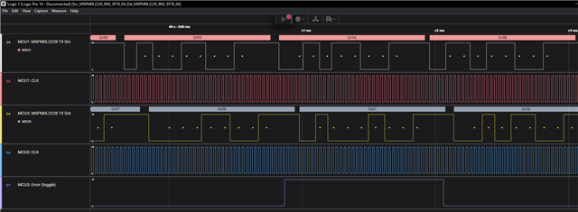
Second picture shows a close up on one of the errors. The byte 0x99 is incorrectly received as 0x91.

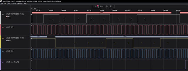
The last picture is further zoomed in so the clocks from both boards are easier to see.

Let me know if more info is needed.

Regards 

Bue

  • Hi,

    Using LFCLK as the clock source of UART would cause significant deviation in the actual baud rate. I would suggest to test with a different clock source and check if you still observe the issue.

    Best regards,

    Cash Hao

  • Hi Cash.

    Thank you very much for your answer. 

    I have now tried with another clock source and running from the HFXT works but since we are developing a low power application that is not a viable option in the long run.

    My question still remains - should it not possible to set up 2x MSPM0L2228 evaluation modules running from LFXT (32.768 kHz) with the exact same UART settings - one for transmitting and one receiving and then expect error free communication between them?

    I know that it should also be possible to use asynchronous fast clock requests when running from ULPCLK but if understand that correctly then the power consumption while receiving and transmitting will be comparable to STOP0 or even higher?

  • My question still remains - should it not possible to set up 2x MSPM0L2228 evaluation modules running from LFXT (32.768 kHz) with the exact same UART settings - one for transmitting and one receiving and then expect error free communication between them?

    If they were using the same 32KHZ clock, yes. If not, then no.

    As shown in you scope captures, bit times are either 3 or 4 clock cycles.

    The receiver detects a start bit and then begins receiving data. But its clock is not aligned with the transmit clock so there can be a lot of delay here. Up to one cycle of the receive clock. In the 3X oversample mode, the receiver samples each bit on its second clock. (Unknown is what its clock looks like.) This puts the sampling time perilously close to the end of the transmitted bit. Add in delay from async clocks and there will be trouble.

    I expect that an 8X oversample mode would work better if a bit slower.

  • Hi David.
    Thank you very much for your answer.
    I have been conducting some more experiments with the MSPM0L2228 clocked by 32.768kHz crystal and it seems that if I set IBRD to 1 and FBRD to 0 thereby getting a baud rate of 10922.67 I am able to transmit and receive between MSPM0L2228-MSPM0L2228, MSPM0L2228-MSP430FR6047 and MSPM0L2228-third party chip without any errors. Does that mean that it is the particular implementation of the baud-rate divisor that is causing all my trouble? And that I should not expect any issues as long as I do not use the fractional part of the baud rate generator (FBRD = 0) - even when µPs are clocked by individual 32.768kHz crystals - or was it just chance that my particular setup worked flawlessly?

    For comparison we have previously successfully had the MSP430FR6047 communicating with the third party chip without errors - in this setup the UART of the MSP430FR6047 was also clocked by 32.768kHz crystal and baud rate was set to 9600 baud without significant issues.

    In regards to the 8X oversample I believe that it would give too low a baud rate for our application.

  • The bit rate generator on the MSP430 is quite different. The modulation pattern is fixed and restarts with each start bit. So if two devices use the same modulation pattern, this works. (9,600 baud from a 32KHz clock will fail if the modulation patterns are different. Or at least it did for me. It took me a while to figure that out.)

    The M0 does something different and the fractional divisor thing suggests a phase accumulator approach. Unsynchronized to the data. So the transmitter adds a cycle of 32KHz here and there while the receiver picks different spots. Disaster.

    Sticking with integer only divisors helps and will work if all devices do the same. But I suspect that margins at the receiver will still be minimal thanks to that sample on the second cycle thing. The bit error rate might not be large but I don't think it will be zero.

  • Hi David.
    Thank you very much for your answer. For now sticking to IBRD = 1 and FBRD = 0 seems to have solved most of the immediate problems.
    However there is one thing more that puzzles me.
    For successfull reception I always have to transmit two stop bits. Either by setting no parity and 2 stop bits - or by setting stick one and 1 stop bit.
    The receiver has to be set up to either no parity and 1 stop bit or stick 1 and 1 stop bit. Setting up the receiver to no parity and 2 stop bits will result in periodic errors.
    What exactly is the difference on the receiver part between no parity and 2 stop bits and stick one and 1 stop bit? I would have assumed that if it was a timing issue that caused the receiver to not be ready before the next frame then stick one and 1 stop bit should also make it fail?

**Attention** This is a public forum