Other Parts Discussed in Thread: MSP430WARE
Tool/software:
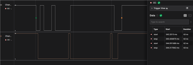
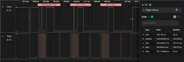
I'm currently using an MSP430G2231 as an I2C slave and have noticed a strange phenomenon:
during I2C communication, if the master sends a write command directly to me, there's a certain chance it will fail.
However, if it first executes a read command and successfully reads the data, the subsequent write command will also complete normally.
I initially suspected that I might be failing to release the interrupt flag somewhere.
I'm using the example code msp430g2x21_usi_15.c and modifying it.
msp430g2x21_usi_15 seem slightly different from MSP430G2231, but can I still use it?
If so, I'm using this example program and still encounter the same problem.
This is my current code:
/* --COPYRIGHT--,BSD_EX
* Copyright (c) 2012, Texas Instruments Incorporated
* All rights reserved.
*
* Redistribution and use in source and binary forms, with or without
* modification, are permitted provided that the following conditions
* are met:
*
* * Redistributions of source code must retain the above copyright
* notice, this list of conditions and the following disclaimer.
*
* * Redistributions in binary form must reproduce the above copyright
* notice, this list of conditions and the following disclaimer in the
* documentation and/or other materials provided with the distribution.
*
* * Neither the name of Texas Instruments Incorporated nor the names of
* its contributors may be used to endorse or promote products derived
* from this software without specific prior written permission.
*
* THIS SOFTWARE IS PROVIDED BY THE COPYRIGHT HOLDERS AND CONTRIBUTORS "AS IS"
* AND ANY EXPRESS OR IMPLIED WARRANTIES, INCLUDING, BUT NOT LIMITED TO,
* THE IMPLIED WARRANTIES OF MERCHANTABILITY AND FITNESS FOR A PARTICULAR
* PURPOSE ARE DISCLAIMED. IN NO EVENT SHALL THE COPYRIGHT OWNER OR
* CONTRIBUTORS BE LIABLE FOR ANY DIRECT, INDIRECT, INCIDENTAL, SPECIAL,
* EXEMPLARY, OR CONSEQUENTIAL DAMAGES (INCLUDING, BUT NOT LIMITED TO,
* PROCUREMENT OF SUBSTITUTE GOODS OR SERVICES; LOSS OF USE, DATA, OR PROFITS;
* OR BUSINESS INTERRUPTION) HOWEVER CAUSED AND ON ANY THEORY OF LIABILITY,
* WHETHER IN CONTRACT, STRICT LIABILITY, OR TORT (INCLUDING NEGLIGENCE OR
* OTHERWISE) ARISING IN ANY WAY OUT OF THE USE OF THIS SOFTWARE,
* EVEN IF ADVISED OF THE POSSIBILITY OF SUCH DAMAGE.
*
*******************************************************************************
*
* MSP430 CODE EXAMPLE DISCLAIMER
*
* MSP430 code examples are self-contained low-level programs that typically
* demonstrate a single peripheral function or device feature in a highly
* concise manner. For this the code may rely on the device's power-on default
* register values and settings such as the clock configuration and care must
* be taken when combining code from several examples to avoid potential side
* effects. Also see www.ti.com/grace for a GUI- and www.ti.com/msp430ware
* for an API functional library-approach to peripheral configuration.
*
* --/COPYRIGHT--*/
//******************************************************************************
// MSP430G2x21/G2x31 - I2C Slave Receiver / Slave Transmitter, multiple bytes
//
// Description: I2C Master communicates with I2C Slave using
// the USI. Master data should increment from 0x55 with each transmitted byte.
// ACLK = n/a, MCLK = SMCLK = Calibrated 1MHz
//
// ***THIS IS THE SLAVE CODE***
//
// Slave Master
// (msp430g2x21_usi_12.c)
// MSP430G2x21/G2x31 MSP430G2x21/G2x31
// ----------------- -----------------
// /|\| XIN|- /|\| XIN|-
// | | | | | |
// --|RST XOUT|- --|RST XOUT|-
// | | | |
// LED <-|P1.0 | | |
// | | | P1.0|-> LED
// | SDA/P1.7|------->|P1.6/SDA |
// | SCL/P1.6|<-------|P1.7/SCL |
//
// Note: internal pull-ups are used in this example for SDA & SCL
//
// D. Dang
// Texas Instruments Inc.
// October 2010
// Built with CCS Version 4.2.0 and IAR Embedded Workbench Version: 5.10
//******************************************************************************
#include <msp430.h>
#include <stdbool.h>
#define Number_of_Bytes 3 // **** How many bytes?? ****
char motor_status=0;
char motor_stepH=0;
char motor_stepL=0;
char motor_up=0;
void Setup_USI_Slave(void);
char MST_Data = 0; // Variable for received data
char SLV_Addr = 0x90; // Address is 0x48<<1 for R/W
char Reg_ptr = 0x00; // current reg.
bool First_wr_reg=0; // First write.
int I2C_State=0, Bytecount=0, transmit = 0; // State variables
void Data_RX(void);
void TX_Data(void);
int main(void)
{
WDTCTL = WDTPW + WDTHOLD; // Stop watchdog
if (CALBC1_1MHZ==0xFF) // If calibration constants erased
{
while(1); // do not load, trap CPU!!
}
DCOCTL = 0; // Select lowest DCOx and MODx settings
BCSCTL1 = CALBC1_1MHZ; // Set DCO
DCOCTL = CALDCO_1MHZ;
Setup_USI_Slave();
//LPM0; // CPU off, await USI interrupt
__no_operation();
}
//******************************************************************************
// USI interrupt service routine
// Rx bytes from master: State 2->4->6->8
// Tx bytes to Master: State 2->4->10->12->14
//******************************************************************************
#if defined(__TI_COMPILER_VERSION__) || defined(__IAR_SYSTEMS_ICC__)
#pragma vector = USI_VECTOR
__interrupt void USI_TXRX (void)
#elif defined(__GNUC__)
void __attribute__ ((interrupt(USI_VECTOR))) USI_TXRX (void)
#else
#error Compiler not supported!
#endif
{
if (USICTL1 & USISTTIFG) // Start entry?
{
I2C_State = 2; // Enter 1st state on start
Bytecount = 0;
USICTL0 &= ~ USIOE;
}
switch(__even_in_range(I2C_State,14))
{
case 0: //USICTL0 &= ~ USIOE; // Idle, should not get here
USICTL0 &= ~USIOE; // SDA = input
SLV_Addr = 0x90; // Reset slave address
Bytecount = 0;
break;
case 2: // RX Address
USICNT = (USICNT & 0xE0) + 0x08; // Bit counter = 8, RX address
USICTL1 &= ~USISTTIFG; // Clear start flag
USICTL1 &= ~USIIFG; // ③ 保險把殘留的 USIIFG 也清掉
USICTL0 &= ~USIOE; // 釋放 SDA(避免你自己拉線)
I2C_State = 4; // Go to next state: check address
break;
case 4: // Process Address and send (N)Ack
if (USISRL & 0x01){ // If master read...
SLV_Addr = 0x91; // Save R/W bit
transmit = 1;}
else{
transmit = 0;
SLV_Addr = 0x90;
}
USICTL0 |= USIOE; // SDA = output
if (USISRL == SLV_Addr) // Address match?
{
USISRL = 0x00; // Send Ack
if (transmit == 0){
I2C_State = 6; // Go to next state: RX data
First_wr_reg=1; //to get current
}
if (transmit == 1){
I2C_State = 10;} // Else go to next state: TX data
}
else
{
USISRL = 0xFF; // Send NAck
SLV_Addr = 0x90; // Reset slave address
I2C_State = 0; // Reset state machine
Bytecount =0; // Reset counter for next TX/RX
}
USICNT |= 0x01; // Bit counter = 1, send (N)Ack bit
break;
case 6: // Receive data byte
Data_RX();
break;
case 8:// Check Data & TX (N)Ack
USICTL0 |= USIOE; // SDA = output
if(First_wr_reg)
{
Reg_ptr=USISRL;
First_wr_reg=0;
}
else
{
switch(Reg_ptr)
{
case 0x11:motor_status = USISRL;break;
case 0x22:motor_stepH = USISRL;break;
}
}
if (Bytecount <= (Number_of_Bytes-2)) // If not last byte
{
USISRL = 0x00; // Send Ack
I2C_State = 6; // Rcv another byte
Bytecount++;
USICNT |= 0x01; // Bit counter = 1, send (N)Ack bit
}
else // Last Byte
{
USISRL = 0xFF; // Send NAck
USICTL0 &= ~USIOE; // SDA = input
SLV_Addr = 0x90; // Reset slave address
I2C_State = 0; // Reset state machine
Bytecount =0; // Reset counter for next TX/RX
}
break;
case 10: // Send Data byte
TX_Data();
break;
case 12:// Receive Data (N)Ack
USICTL0 &= ~USIOE; // SDA = input
USICNT |= 0x01; // Bit counter = 1, receive (N)Ack
I2C_State = 14; // Go to next state: check (N)Ack
break;
case 14:// Process Data Ack/NAck
if (USISRL & 0x01) // If Nack received...
{
USICTL0 &= ~USIOE; // SDA = input
SLV_Addr = 0x90; // Reset slave address
I2C_State = 0; // Reset state machine
Bytecount = 0;
// LPM0_EXIT; // Exit active for next transfer
}
else // Ack received
{
TX_Data(); // TX next byte
}
break;
}
USICTL1 &= ~USIIFG; // Clear pending flags
}
void Data_RX(void){
USICTL0 &= ~USIOE; // SDA = input
USICNT |= 0x08; // Bit counter = 8, RX data
I2C_State = 8; // next state: Test data and (N)Ack
}
void TX_Data(void){
switch(Reg_ptr)
{
case 0x11:USISRL=motor_status;break;
case 0x22:USISRL=motor_stepH ;break;
default:
USISRL=0xFF;break;
}
USICTL0 |= USIOE; // SDA = output
USICNT |= 0x08; // Bit counter = 8, TX data
I2C_State = 12; // Go to next state: receive (N)Ack
}
void Setup_USI_Slave(void){
P1OUT = 0xC0; // P1.6 & P1.7 Pullups
P1REN |= 0xC0; // P1.6 & P1.7 Pullups
P1DIR = 0xFF; // Unused pins as outputs
P2OUT = 0;
P2DIR = 0xFF;
USICTL0 = USIPE6+USIPE7+USISWRST; // Port & USI mode setup
USICTL1 = USII2C+USIIE+USISTTIE; // Enable I2C mode & USI interrupts
USICKCTL = USICKPL; // Setup clock polarity
USICNT |= USIIFGCC; // Disable automatic clear control
USICTL0 &= ~USISWRST; // Enable USI
USICTL1 &= ~USIIFG; // Clear pending flag
transmit = 0;
__enable_interrupt();
}