MSP430FR5043: about the stop pulses with Multi Tone Generation

Part Number: MSP430FR5043

Tool/software:

《MSP430FR58xx, MSP430FR59xx, and MSP430FR6xx Family User's Guide》21.2.5 Multi Tone Generation described:

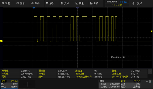
Finally setting SAPH_AXPGCTL.XMOD = 2 to terminates the multi tone. The last regular excitation pulses
are followed by stop pulses. Then PPG_A goes to Pause phase again (see Figure 21-10 and Figure 21-9).
The stop pulses have a 180° phase shift compared to the last regular excitation pulses. The stop pulses
have same frequency as the last regular excitation pulses。

to my understanding,stop pulses has two important attributes:180° phase shift and same frequency, compared to the last regular excitation pulses 
This also conforms to the accompanying diagram in the document:

(Figure 21-11. PPG_A Multi Tone Generation With SAPHPGC.PPOL = 1(Starts With Low Polarity))

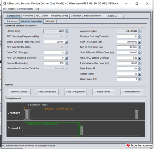
However, in the example routines provided on the official website, the frequency of the "stop pulses" section is pre-defined. This configuration refers to the following preset settings, which do not conform to the documentation instructions:

const USS_App_AddlTXSequence_t addtlTXSeqs[USS_APP_ADDTL_TX_SEQUENCES_MAX] =
{
// Sequence # 1
// 2 trill pulses
// X-Pulse #1 = 1 @300kHz (with 80Mhz PLL)
// E-Pulse #1 = 1 @400kHz (with 80Mhz PLL)
// X-Pulse #2 = 2 @500kHz (with 80Mhz PLL)
// E-Pulse #2 = 2 @500kHz (with 80Mhz PLL)
{
.numTrillCycles = 2,
.xpulse = {1,2},
.xhper = {133,80},
.xlper = {133,80},
.epulse = {1,2},
.ehper = {100,80},
.elper = {100,80},
.binPatternLen = 14,
.binPattern = {1,1,-1,-1,1,-1,1,-1,1,-1,1,-1,1,-1}
},
// Sequence # 2
// 2 trill pulses
// X-Pulse #1 = 1 @300kHz (with 80Mhz PLL)
// E-Pulse #1 = 1 @400kHz (with 80Mhz PLL)
// X-Pulse #2 = 2 @500kHz (with 80Mhz PLL)
// E-Pulse #2 = 2 @800kHz (with 80Mhz PLL)
{
.numTrillCycles = 2,
.xpulse = {1,2},
.xhper = {133,80},
.xlper = {133,80},
.epulse = {1,2},
.ehper = {100,50},
.elper = {100,50},
.binPatternLen = 25,
.binPattern = {1,1,1,1,-1,-1,-1,1,1,1,-1,-1,1,1,-1,-1,1,1,-1,-1,1,-1,-1,1,-1}
}
};

I would like to confirm whether the code in this part needs to be adjusted by the manufacturer based on the actual working frequency of the product?

  • I misunderstood, 

    const USS_App_AddlTXSequence_t addtlTXSeqs[USS_APP_ADDTL_TX_SEQUENCES_MAX] 

    is used for test tone。

    so how to turn off  the test tone in automatic mode?

    and how to turn on the stop pluses  in automatic mode?

  • Let me loop the USS expert to provide comments.

  • I am currently conducting tests based on the sample code downloaded from the official website.
    I hope to receive assistance and be guided on how to make modifications to the routine code to achieve my goal.
    thanks.

  • Hi,

    What is your goal here. I am unclear about what you want to do?

    Best regards,

    Cash Hao

  • I use msp430fr5043 for gas meter. I followed the instructions of the document "Software changes required for MSP430FR5043.pdf " and it worded.

    but during the measurement process, I observed that the DTOF window sometimes undergoes sudden changes,like this:

    It often occurs during periods of big flow.

    I need to find out the cause of this phenomenon and then solve it.

    I have two ideas of my own:

    one is the flow channel causes sound wave reflection, and the other is the ultrasound excitation pulse.

    Regarding the first reason, I will improve the flow channel and then conduct further observation.

    then,about the ultrasound excitation pulse, my ultrasonic transducer operates at a frequency of 500 KHz.

    I use the follow setting:

    the ADC Capture like this at 0 flow:

    and this at 6m3/h flow:

     .

    I observed the excitation signal through the oscilloscope as follows:

    except 8 x-pulse and e-pulse, There are an additional 6 pulsesn, and no s-pulse.

    I think this additional pulse might be the cause.

    I found the definitions of these 6 pulses in the code:

    const USS_App_AddlTXSequence_t addtlTXSeqs[USS_APP_ADDTL_TX_SEQUENCES_MAX] =
    {
    // Sequence # 1
    // 2 trill pulses
    // X-Pulse #1 = 1 @300kHz (with 80Mhz PLL)
    // E-Pulse #1 = 1 @400kHz (with 80Mhz PLL)
    // X-Pulse #2 = 2 @500kHz (with 80Mhz PLL)
    // E-Pulse #2 = 2 @500kHz (with 80Mhz PLL)
    {
    .numTrillCycles = 2,
    .xpulse = {1,2},
    .xhper = {133,80},
    .xlper = {133,80},
    .epulse = {1,2},
    .ehper = {100,80},
    .elper = {100,80},
    .binPatternLen = 14,
    .binPattern = {1,1,-1,-1,1,-1,1,-1,1,-1,1,-1,1,-1}
    },
    // Sequence # 2
    // 2 trill pulses
    // X-Pulse #1 = 1 @300kHz (with 80Mhz PLL)
    // E-Pulse #1 = 1 @400kHz (with 80Mhz PLL)
    // X-Pulse #2 = 2 @500kHz (with 80Mhz PLL)
    // E-Pulse #2 = 2 @800kHz (with 80Mhz PLL)
    {
    .numTrillCycles = 2,
    .xpulse = {1,2},
    .xhper = {133,80},
    .xlper = {133,80},
    .epulse = {1,2},
    .ehper = {100,50},
    .elper = {100,50},
    .binPatternLen = 25,
    .binPattern = {1,1,1,1,-1,-1,-1,1,1,1,-1,-1,1,1,-1,-1,1,1,-1,-1,1,-1,-1,1,-1}
    }
    };

    My question is:

    1、Your explanation for the cause of this mutation phenomenon;

    2、what is the  additional 6 pulses,is Test Tone Generation described in the chapter 21.2.8 of "MSP430FR6xx Family User's Guide "?

    and how do I turn this off additional pulses in the code?

    3、I want to test the effect of the stop pulse,how do i turn on it in the code in the auto mode?

  • Supplementary configuration diagram:

  • It looks like there is cycle slip issue on the TOF results. I think it is related to the 500k transducer. I would suggest to change to 200kHz transducer. It will significantly lower the cycle slip issue rate.  

    The additional 6 pulses should be the stop pulses. It can be controlled by the User Param#8.

  • The 500KHz transducer is the highlight of our product,we can't change it.
    Any other I can do?
    Furthermore, if the cause of the cycle slip  is the excessively high frequency, would there be the same problem in the water meter with a higher frequency?

  • The issue is that this transducer you are using is not that sensitive to the excitation pulses. I would assume you are testing with air. And you will need 12.2dB PGA gain setting to get a proper ADC capture data in air. If you change air to methane or other gases, you will need a higher PGA gain setting. It is not what we want here. A higher PGA gain setting means the original signal is small with poor SNR. A signal with noise would cause cycle slip issue you are seeing here. If you keep want to use 500kHz transducer, then try with a different manufacture. The current one does not fit USS solution. 

  • According to my previous research, the piezoelectric ceramic transducers used in gas meters are difficult to receive sufficient signal amplitude without amplification.I compared the piezoelectric ceramic transducers  manufacturer mentioned in your document,the sensitivity of the piezoelectric ceramic transducer I am currently using is 10 times that of JIAKANG's.

    The  ultrasonic signal receiving I am testing currently does not use an amplification circuit. Instead, it directly feeds the signal into the MCU through a 1nF capacitor。

    If I add a gain amplification circuit , will it help solve this problem?Additionally, I would like to know, is there any difference between using the external amplification circuit  and the internal gain of the MCU?

  • The internal PGA performance is not as good as an external one especially when the PGA gain is high. 

  • All right, I will try out some ideas. If there are any further questions, I will contact you again.

**Attention** This is a public forum