


Part Number: MSP430FR5962
#include <msp430fr5962.h>
#include <msp430.h> // Adjust for your MCU
#include <stdint.h>
#include "math.h"
#define SLAVE_ADDR 0x65 // 7-bit slave address
#define max_buff 32
#define NUM_SLAVES 3
UINT8 SlaveAddr[NUM_SLAVES] = {0x65, 0x0B, 0x0C};
volatile UINT8 SlaveFlag = 0;
#define I2C_TIMEOUT 10
UINT8 buffer;
volatile UINT8 *i2c_tx_ptr = 0,*i2c_rx_ptr=0;
volatile UINT8 i2c_tx_len = 0,i2c_rx_len=0,tx_count=0;
volatile UINT8 i2c_done = 0;
volatile UINT8 i2c_ack_rev = 1;
volatile UINT8 i2c_busy = 0;
volatile UINT8 i2c_result = 0; // 0 = success, 1 = NACK, 2 = busy
volatile UINT8 rx_count = 0;
//******************************************************************************
// General I2C State Machine ***************************************************
//******************************************************************************
/* Used to track the state of the software state machine*/
I2C_Mode MasterMode = IDLE_MODE;
/* The Register Address/Command to use*/
UINT8 TransmitRegAddr = 0;
volatile UINT8 i2c_timeout = 0;
UINT8 ReceiveBuffer[MAX_BUFFER_SIZE] = {0};
UINT8 RXByteCtr = 0;
UINT8 ReceiveIndex = 0;
UINT8 TransmitBuffer[MAX_BUFFER_SIZE] = {0};
UINT8 TXByteCtr = 0;
UINT8 TransmitIndex = 0;
i2c_transmission_reception_wait(void )
{
while(i2c_busy )
{
}
}
void i2c_init(void)
{
UCB2CTLW0 = UCSWRST;
// Configure as I2C master, synchronous mode
UCB2CTLW0 |= UCMST | UCMODE_3 | UCSYNC;
// Use SMCLK = 16 MHz
UCB2CTLW0 |= UCSSEL__SMCLK;
// Baud rate = SMCLK / UCB2BRW (100 kHz: 16,000,000 / 100,000 = 160)
UCB2BRW = 40;
// Route SDA/SCL pins (P7.0 = SDA, P7.1 = SCL)
P7SEL0 |= BIT0 | BIT1;
P7SEL1 &= ~(BIT0 | BIT1);
// Release eUSCI_B2 from reset
UCB2CTLW0 &= ~UCSWRST;
// Enable TX, RX, and NACK interrupts
UCB2IE = UCTXIE0 | UCRXIE0 | UCNACKIE;
}
void CopyArray(UINT8 *source, UINT8 *dest, UINT8 count)
{
UINT8 copyIndex = 0;
for (copyIndex = 0; copyIndex < count; copyIndex++)
{
dest[copyIndex] = source[copyIndex];
}
}
// Add "UINT8 *rx_buf" argument
I2C_Mode i2c_start_rx(UINT8 addr, UINT8 cmd, UINT8 data_len, UINT8 *rx_buf)
{
i2c_transmission_reception_wait();
MasterMode = TX_REG_ADDRESS_MODE;
TransmitRegAddr = cmd;
RXByteCtr = data_len;
TXByteCtr = 0;
ReceiveIndex = 0;
TransmitIndex = 0;
if(addr == FLAME_SENSOR)
{
i2c_rx_ptr = flame_buf ;
}
else if(addr == SR_SENSOR)
{
i2c_rx_ptr = sr_buf ;
}
else
{
i2c_rx_ptr = hr_buf ;
}
i2c_rx_ptr = rx_buf; // Assign the user buffer
/* Initialize slave address and interrupts */
UCB2I2CSA = addr;
UCB2IFG &= ~(UCTXIFG + UCRXIFG); // Clear any pending interrupts
UCB2IE &= ~UCRXIE; // Disable RX interrupt
UCB2IE |= UCTXIE; // Enable TX interrupt
UCB2CTLW0 |= UCTR + UCTXSTT; // I2C TX, start condition
i2c_busy = TRUE ;
i2c_timeout = 5;
return MasterMode;
}
I2C_Mode i2c_start_tx(UINT8 slave_addr,UINT8 cmd, UINT8 *data, UINT8 length)
{
/* Initialize state machine */
i2c_transmission_reception_wait();
MasterMode = TX_REG_ADDRESS_MODE;
TransmitRegAddr = cmd;
//Copy register data to TransmitBuffer
CopyArray(data, TransmitBuffer, length);
TXByteCtr = length;
RXByteCtr = 0;
ReceiveIndex = 0;
TransmitIndex = 0;
/* Initialize slave address and interrupts */
UCB2I2CSA = slave_addr ;
UCB2IFG &= ~(UCTXIFG + UCRXIFG); // Clear any pending interrupts
UCB2IE &= ~UCRXIE; // Disable RX interrupt
UCB2IE |= UCTXIE; // Enable TX interrupt
UCB2CTLW0 |= UCTR + UCTXSTT; // I2C TX, start condition
i2c_busy = TRUE ;
i2c_timeout = 5;
return MasterMode;
}
#pragma vector = USCI_B2_VECTOR
__interrupt void USCI_B2_ISR(void)
{
UINT8 rx_val = 0;
switch (__even_in_range(UCB2IV, USCI_I2C_UCBIT9IFG))
{
case USCI_I2C_UCRXIFG0: // RXIFG0
rx_val = UCB2RXBUF;
if (RXByteCtr)
{
i2c_rx_ptr[ReceiveIndex++] = rx_val; // store into user buffer
RXByteCtr--;
}
if (RXByteCtr == 1)
{
UCB2CTLW0 |= UCTXSTP; // schedule stop for last byte
// i2c_busy = FALSE; // important — allow TX to continue
}
else if (RXByteCtr == 0)
{
UCB2IE &= ~UCRXIE;
MasterMode = IDLE_MODE;
i2c_busy = FALSE;
i2c_rx_ptr = 0; // clear pointer after done
}
break;
case USCI_I2C_UCNACKIFG: // NACK received
UCB2CTLW0 |= UCTXSTP; // send stop
UCB2IFG &= ~UCNACKIFG; // clear NACK flag
// MasterMode = IDLE_MODE;
// i2c_rx_ptr = 0; // clear pointer (optional)
i2c_busy = FALSE; // important — allow TX to continue
break;
case USCI_I2C_UCTXIFG0: // Vector 24: TXIFG0
switch (MasterMode)
{
case TX_REG_ADDRESS_MODE:
UCB2TXBUF = TransmitRegAddr;
if (RXByteCtr)
MasterMode = SWITCH_TO_RX_MODE; // Need to start receiving now
else
MasterMode = TX_DATA_MODE; // Continue to transmision with the data in Transmit Buffer
break;
case SWITCH_TO_RX_MODE:
UCB2IE |= UCRXIE; // Enable RX interrupt
UCB2IE &= ~UCTXIE; // Disable TX interrupt
UCB2CTLW0 &= ~UCTR; // Switch to receiver
MasterMode = RX_DATA_MODE; // State state is to receive data
UCB2CTLW0 |= UCTXSTT; // Send repeated start
if (RXByteCtr == 1)
{
//Must send stop since this is the N-1 byte
while((UCB2CTLW0 & UCTXSTT));
UCB2CTLW0 |= UCTXSTP; // Send stop condition
}
break;
case TX_DATA_MODE:
if (TXByteCtr)
{
UCB2TXBUF = TransmitBuffer[TransmitIndex++];
TXByteCtr--;
}
else
{
//Done with transmission
UCB2CTLW0 |= UCTXSTP; // Send stop condition
MasterMode = IDLE_MODE;
UCB2IE &= ~UCTXIE; // disable TX interrupt
}
break;
default:
UCB2IFG = 0;
__no_operation();
break;
}
break;
default: break;
}
}
int main(void)
{
UINT8 flag = FALSE, counter = 0;
UINT8 buf[11];
UINT8 rx_buffer[8],rx_buffer1[8],rx_buffer2[8]; // Buffer for received data
UINT8 cmd = 0x04; // Command to send before reading
i2c_init();
while (1)
{
watch_clr();
i2c_start_rx(0xA0 , 0X65, 5 ,rx_buffer);
i2c_start_rx(0xA1 , 0X65, 5 ,rx_buffer1);
i2c_start_rx(0xA2 , 0X65, 5 ,rx_buffer2);
}
}
Hello Support Team,
I am facing an issue with my controller during I²C operation.
The controller boots normally and initializes without any problem.
However, after I²C communication starts, the controller resets unexpectedly after some time and enters a continuous reset loop.
Summary of the issue:
-
Controller initializes successfully
-
I²C communication starts
-
After some time, the controller resets by itself
-
The reset repeats continuously
- And also if my bus line seem low when initating .then communication is not happening like continous reset .
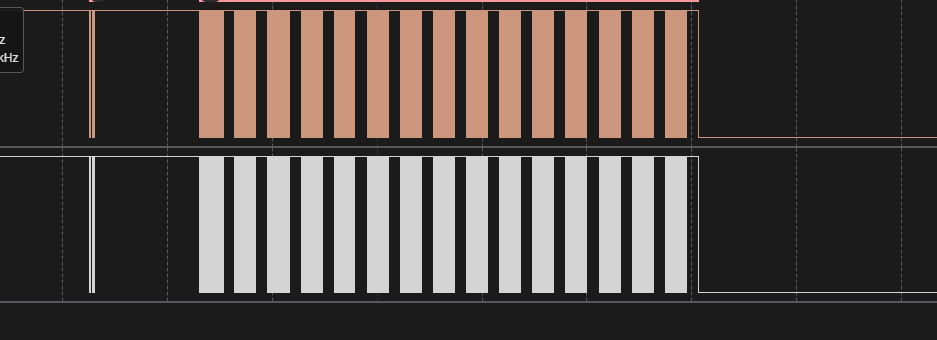 Please advise what might be causing this issue. I can share logs, wiring diagrams, firmware details, or any additional information if needed.
Thank you.
