Part Number: MSP430F6775A
Hello,
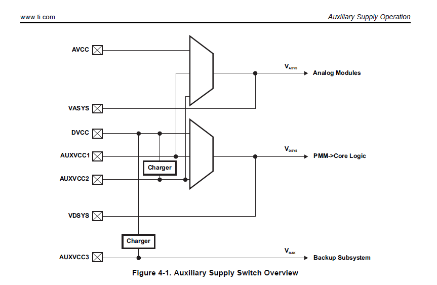
We have an application developed using the MSP430F6775A. Unlike most other MSP430 MCUs, this device includes an internal Auxiliary Supply Switch module. As shown in the block diagram, the main supply of the processor is selected from DVCC, AUXVCC1, and AUXVCC2.
In our application:
-
DVCC is supplied from the 230 VAC mains and regulated to 3.3V.
-
AUXVCC1 is connected to a 3.6 V battery and supplies the MCU when the mains power is unavailable.
-
AUXVCC2 is left unconnected.
During production programming of this MCU, we can either supply power from the GANG programmer or use the on-board batteries. I have questions for both scenarios.
Scenario 1: Power supplied by the GANG programmer
When the supply is generated by the GANG:
-
Should JTAG pin 2 (the pin through which the GANG supplies power to the target) be connected to DVCC, or to VDSYS, which is the output of the auxiliary supply switch?
-
If the auxiliary supply switch is functional and active during JTAG programming, then connecting to DVCC would make sense.
-
However, if the module is inactive during programming, then the connection should be made to VDSYS.
Unfortunately, the datasheet does not provide any information about the state or behavior of this module during JTAG programming.
-
-
In the same scenario, would it be possible to connect the GANG supply pin (JTAG pin 2) to the unused AUXVCC2 pin, such that when neither the mains supply nor the battery are present, the MCU would be powered by the GANG through this pin?
Scenario 2: Power supplied internally, sensed by the GANG
In this scenario, the MCU is powered internally via the mains supply or the battery, and the GANG only senses the target voltage.
-
In this case, should the JTAG sense pin (pin 4) be connected to VDSYS?
-
However, if the auxiliary supply switch does not operate during programming, the programmer may not detect any voltage on VDSYS, which could cause the programming operation to fail.
All TI JTAG programming documentation appears to ignore MSP430 devices that include the auxiliary supply switch module, and no guidance is provided for such cases. We would appreciate your clarification on the correct and recommended way to use the GANG programmer with this MCU, considering the auxiliary supply architecture.
Thank you in advance for your support.