This thread has been locked.

If you have a related question, please click the "Ask a related question" button in the top right corner. The newly created question will be automatically linked to this question.

MSPM0L1117: Inconsistent TimerG0 interrupt period when using LFOSC on MSPM0L1117

Part Number: MSPM0L1117
Other Parts Discussed in Thread: , 4428

Hello,

I am currently working on a proof-of-concept device and have encountered unexpected behavior that I do not fully understand. At this stage, I am using the LP-MSPM0L1117 LaunchPad, as it is sufficient to evaluate whether the MCU meets my requirements.

My primary goals are achieving the lowest possible power consumption on the MSPM0L1117 while maintaining accurate time measurements. To minimize power usage, the device enters Standby1 mode. According to the documentation, TimerG0 is available in this mode, so I am using it as the time base.

To reduce BOM cost, the timer is clocked from the internal LFOSC rather than an external LFXT. I ported timing-related code from another MCU that has been used successfully on devices from multiple manufacturers. However, on the MSPM0L1117, the behavior is inconsistent.

After further investigation, I isolated a minimal example that demonstrates the issue. TimerG0 is configured with an overflow interrupt at 0xFFFF and runs at the full LFOSC frequency (~32 kHz), while the device remains in Run mode (i.e. without entering Standby1). In the interrupt service routine, I toggle a GPIO pin and monitor the pin using a Saleae logic analyzer.

The expected period between GPIO toggles is approximately 2 seconds. In practice, however, the interval varies by up to 900 µs. I have not observed this type of behavior on MCUs from other manufacturers that I have worked with.

I understand that the LFOSC accuracy is specified at approximately ±3%, so I do not expect the period to be exactly 2 seconds. However, I do not understand why the interrupt does not occur at a constant period. When I route the LFOSC clock to an output pin and measure it, the frequency appears stable at approximately 33 kHz.

When I switch to the external crystal oscillator available on the LaunchPad, the interrupt period becomes stable and highly precise, with a maximum variation of about 30 µs, which is acceptable and expected.

Is there anything I might be missing regarding the use of LFOSC with TimerG0, particularly with respect to clock stability, synchronization, or low-power modes? Are there any known limitations or configuration details that could explain this behavior, or any recommended methods to achieve more stable timing when using LFOSC?


timingIssues.png

  • My first thought is that 900usec in 2 seconds is about 0.045% (450ppm), which is pretty good for a 3% clock. The 33kHz you mentioned is 0.7%, which is actually worse than the 900usec measurement.

    Are you running the CPU from LFCLK in your RUN-mode experiment? At 32kHz, 900usec is about 30 CPU clocks; that's pretty easy to use up if you have any conditionals (if() e.g.) in your ISR. It might be interesting to see what a timer output (PWM) looks like when driven from LFOSC.

  • Hi Krzysztof,

    I would first ensure that there is a clean and stable power supply to the device. I don't expect this to be the cause of any jitter you are observing, but it is always a good first place to look.

    Do you observe the same variation with shorter timer periods? You could try shorter timer periods and maintain a software counter.

     Best,

    Owen

  • Hi Owen,

    I've not tried other power supply.
    I'm using TI launchpad LP-MSPM0L1117 so power is delivered from USB. I will try other sources but I don't think it would help.

    I can try set load interrupt with different values than 0xffff to see if behavior will change, but I've tried with capture interrupt with different settings and I also could see that period changes even though compare value stays the same.

  • Hi Bruce,

    Thanks for you answer.

    CPU runs from SYSOSC at full 32MHz. Currently I'm not switching to low power modes.
    LFCLK is used only to drive timerG0, everything else runs as fast as it can.


    I can see that both load and capture interrupts are giving different period between pin state change, even though it should be stable.
    It is enough to change LFCLK to use LFXT as a clock source to resolve this issue with different periods. No other code changes are required to get expected behavior.

    void SystemTimer_INST_IRQHandler( void )
    {
      DL_TIMER_IIDX intSource = DL_TimerA_getPendingInterrupt( SystemTimer_INST );
      DL_Timer_clearInterruptStatus( SystemTimer_INST, intSource );
    
      HAL_SYSTEM_SystickEvent_t event;
      switch ( intSource )
      {
        case DL_TIMER_IIDX_LOAD:
        {
          lastState = !lastState;
          HAL_GPIO_LedPinState( lastState );
          event = HAL_SYSTEM_EVENT_OVF;
          break;
        }
    
        case DL_TIMER_IIDX_CC0_UP:
        {
          event = HAL_SYSTEM_EVENT_COMP;
          break;
        }
    
        default:
          return;
      }
    
      if ( systickCallback != NULL )
      {
        systickCallback( event );
      }
    }

    Other interrupts in the system, should not happen, so timer interrupt are not being blocked by other interrupts.
    Callback is not defined so also should not have influence on interrupts.

    I can't believe the clock signal is so variable, especially since it appears stable when exposed to the pin. It's not 32,768 Hz, just a bit higher, but stable (as far as I can tell from looking at the graphs on saleae).

  • HI Krzysztof,

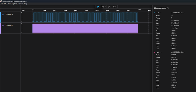
    I implemented a similar application, where I source TIMG0 from LFCLK (LFOSC) with a 2s period (0xFFFF load) and toggle PA0 within the IRQ. I set the Low Power Mode policy to STANDBY1. I am also outputting the LFCLK on the CLK_OUT pin (PA10). I am not seeing as much variation as you are observing, so I was wondering what pin you are outputting your GPIO signal on and if there are any circuitry on the LaunchPad that could be interfering with this output.

    GPIO Toggle:

    ΔT 100.13638656 s
    Nfalling 25
    Nrising 25
    fmin 0.2513438261036116 Hz
    fmax 0.2513815035028177 Hz
    fmean 0.2513618401170737 Hz
    Tstd 0.00016319663977866467 s
    Hmin 1.9889740400000009 s
    Hmean 1.989161924 s
    HSDev 0.00008598741845826281 s
    Hmax 1.9893153600000004 s
    Lmin 1.9890292199999995 s
    Lmean 1.9891648858333335 s
    LSDev 0.00008481288345426218 s
    Lmax 1.9892983800000001 s

    Hmax - Hmin = 341.3199999995 us

    Lmax - Lmin = 269.1600000006 us

    CLK_OUT:

    ΔT 100.13638656 s
    Nfalling 3299147
    Nrising 3299148
    fmin 32894.73683855294 Hz
    fmax 33003.30034748091 Hz
    fmean 32946.54378319972 Hz
    Tstd 1.145919948211834e-8 s
    Hmin 0.000015139999988605268 s
    Hmean 0.000015178020015812729 s
    HSDev 8.831878208322769e-9 s
    Hmax 0.000015220000001136213 s
    Lmin 0.000015139999974053354 s
    Lmean 0.000015174177368118403 s
    LSDev 9.65117057980261e-9 s
    Lmax 0.000015200000008917441 s

    /*
     * Copyright (c) 2021, Texas Instruments Incorporated
     * All rights reserved.
     *
     * Redistribution and use in source and binary forms, with or without
     * modification, are permitted provided that the following conditions
     * are met:
     *
     * *  Redistributions of source code must retain the above copyright
     *    notice, this list of conditions and the following disclaimer.
     *
     * *  Redistributions in binary form must reproduce the above copyright
     *    notice, this list of conditions and the following disclaimer in the
     *    documentation and/or other materials provided with the distribution.
     *
     * *  Neither the name of Texas Instruments Incorporated nor the names of
     *    its contributors may be used to endorse or promote products derived
     *    from this software without specific prior written permission.
     *
     * THIS SOFTWARE IS PROVIDED BY THE COPYRIGHT HOLDERS AND CONTRIBUTORS "AS IS"
     * AND ANY EXPRESS OR IMPLIED WARRANTIES, INCLUDING, BUT NOT LIMITED TO,
     * THE IMPLIED WARRANTIES OF MERCHANTABILITY AND FITNESS FOR A PARTICULAR
     * PURPOSE ARE DISCLAIMED. IN NO EVENT SHALL THE COPYRIGHT OWNER OR
     * CONTRIBUTORS BE LIABLE FOR ANY DIRECT, INDIRECT, INCIDENTAL, SPECIAL,
     * EXEMPLARY, OR CONSEQUENTIAL DAMAGES (INCLUDING, BUT NOT LIMITED TO,
     * PROCUREMENT OF SUBSTITUTE GOODS OR SERVICES; LOSS OF USE, DATA, OR PROFITS;
     * OR BUSINESS INTERRUPTION) HOWEVER CAUSED AND ON ANY THEORY OF LIABILITY,
     * WHETHER IN CONTRACT, STRICT LIABILITY, OR TORT (INCLUDING NEGLIGENCE OR
     * OTHERWISE) ARISING IN ANY WAY OUT OF THE USE OF THIS SOFTWARE,
     * EVEN IF ADVISED OF THE POSSIBILITY OF SUCH DAMAGE.
     */
    
    #include "ti_msp_dl_config.h"
    
    int main(void)
    {
        SYSCFG_DL_init();
    
        NVIC_EnableIRQ(TIMER_0_INST_INT_IRQN);
    
        DL_TimerG_startCounter(TIMER_0_INST);
    
        while (1) {
            __WFI();
        }
    }
    
    void TIMER_0_INST_IRQHandler(void)
    {
        switch (DL_TimerG_getPendingInterrupt(TIMER_0_INST)) {
            case DL_TIMER_IIDX_LOAD:
                DL_GPIO_togglePins(GPIO_GRP_0_PORT, GPIO_GRP_0_PIN_0_PIN);
                break;
            default:
                break;
        }
    }

    https://e2e.ti.com/cfs-file/__key/communityserver-discussions-components-files/166/4428.empty.syscfg

    Best,

    Owen

  • Hi Owen,

    Sorry for late response, too much going on right now in other work.

    I can see that variations in you case are lower, but still 300us for the project I would like to use this MCU in, is a little too big.

    Could you tell me if variations are lower with shorter periods of time, if yes then how it looks like in delays like 1ms, 10ms ?

    ClkOut - PA14
    ToggledPin - PB6

    TOGGLE
    ΔT 1472.5906173296034 s
    Nfalling 371
    Nrising 371
    fmin 0.25189899980630714 Hz
    fmax 0.2520096261931451 Hz
    fmean 0.2519422577827418 Hz
    Tstd 0.0003129457918991747 s
    TposMean 1.9845758564151021
    TposMin 1.983669198000105
    TposMax 1.9849666960000758
    TnegMean 1.984588374464857
    TnegMin 1.9838134019999998
    TnegMax 1.98493283200007858320000785
    Dutymean 0.4999983238400206
    Dutymin 0.49989151061575204
    Dutymax 0.5001071055750572
    fmean 0.2519422593447552
    fmin 0.25189899980630714
    fmax 0.2520096261931451
    Pmin 3.9680408960001077 s
    Pmean 3.9691637058918916 s
    PSDev 0.0003079089944625446 s
    Pmax 3.9698303440000164 s
    Count 370

    TposMax - TposMin = 1297us
    TnegMax - TnegMin = 1119us

    I will be probably forced to use external xtal.

    Thanks,
    Chris

  • Hi Chris,

    Here is the data I collected for a 1ms period:

    ΔT 60.09520128 s
    Nfalling 29997
    Nrising 29997
    fmin 498.89494769155465 Hz
    fmax 499.32341676829736 Hz
    fmean 499.15623069081636 Hz
    Tstd 3.0677628628323143e-7 s
    Hmin 0.00100125000000844 s
    Hmean 0.0010016915078676957 s
    HSDev 1.660477399697086e-7 s
    Hmax 0.0010022499999995489 s
    Lmin 0.0010012600000045494 s
    Lmean 0.001001689278261173 s
    LSDev 1.6539438680088583e-7 s
    Lmax 0.001002280000004248 s

    H_range 1.000
    L_range 1.02

    The ranges above are in us.

    Here is the data I collected for a 10ms period:

    ΔT 60.12862463999999 s
    Nfalling 3020
    Nrising 3020
    fmin 50.20322264526634 Hz
    fmax 50.23911305860242 Hz
    fmean 50.22425886026334 Hz
    Tstd 0.0000023149613833022066 s
    Hmin 0.009951789999999164 s
    Hmean 0.009955338671745627 s
    HSDev 0.000001329100351714825 s
    Hmax 0.009960460000002058 s
    Lmin 0.009952139999999417 s
    Lmean 0.0099553583841059 s
    LSDev 0.000001326370186367275 s
    Lmax 0.00995973999999842 s

    H_range 8.670
    L_range 7.6

    The ranges above are in us.

    Best,

    Owen

**Attention** This is a public forum