Part Number: MSP430FR2676
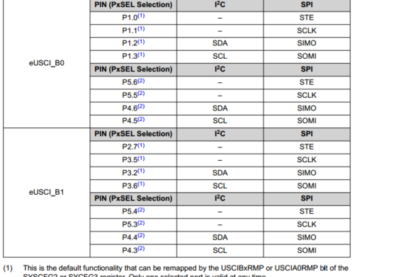
Setting 1) eUSCI_B0 → SPI SCLK = P5.5, SIMO = P4.6, SOMI = P4.5 eUSCI_B1 → I2C SDA = P3.2, SCL = P3.6
Setting 2) eUSCI_B0 → SPI SCLK = P5.5, SIMO = P4.6, SOMI = P4.5 eUSCI_B1 → I2C SDA = P4.4, SCL = P4.3
The I2C device worked with Setting 1, but not with Setting 2. Is this pattern wrong?
Setting 1) P3SEL0 |= 0x44; P3SEL1 &= ~0x44;
Setting 2) P4SEL0 |= 0x18; P4SEL1 &= ~0x18;
The main difference is the source code shown above. The I2C slave is the same, only the CPU connection is different.