This thread has been locked.

If you have a related question, please click the "Ask a related question" button in the top right corner. The newly created question will be automatically linked to this question.

MSP430F6779A: MSP430 Reset and Damage Issue

Part Number: MSP430F6779A

We are using MSP430F6779AIPZ design in our EVSE design. Whenever we are probing any pins with multimeter or oscilloscope sometimes the controller resets and when we probe the reset signals then the waveform is like below. Displaying image.png 

Sometimes the controller also gets damaged and I am not sure this may be the reason for that. Kindly let me know if additional details are required.

  • Hi Suresh,

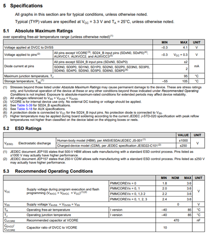
    I would ensure that there are no violations to the absolute maximum ratings:

    The waveform that you attached is not appearing for me. Could you re-send it?

    What signals from the oscilloscope are you inputting to the device? Which pins?

    Are you using proper ESD protection? Are you using a high-impedance probe?

    Feel free to also share your schematic with your local technical sales representative or field applications engineer if you would like a review.

    Best,

    Owen

  • Hi Owen Li,

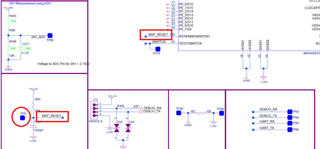
    I am probing at TP9(which is connected to pin no 100 of MSP430F6779AIPZ) using Tektronix TPP0200 Voltage probe(20MHz / 10Mohm / <12pF / 10X / 300V CAT II).

    I hope now you can see the attached waveform. 

    Also, I have tried powering the board by external 3.3V using Regulated Power Supply but still the issue persist when I am touching any voltage line/AC Line or touching any pins or pad in the board.

  • Hi Suresh,

    From your schematic, I would use the recommended 10nF (10000pF) capacitor on the RST pin rather than the current 1000pF.

    I would also ensure you have the proper decoupling capacitors.

    From your waveforms, it appears that transients up to 5.46V are being applied to the pin. Firstly, this exceeds the absolute maximum conditions outlined in the device-specific datasheet. This could very well explain why the device resets or is damaged.

    What is causing these transients to appear? Does it happen when you probe the pin? Is there some other event or action that takes place?

    Best,

    Owen

  • Hi Owen Li,

    This is happenning whenever I touch any conductive area in the board(Pins, Copper Pads, AC Line) by Multimeter probe or Oscilloscope probe or with a normal wire. 

  • Hi Suresh,

    This sounds like it may be an issue with the design of the board.

    Some things to consider:

    • Ensure proper grounding (i.e. solid ground plains)
    • Keep reset traces short and away from switching circuits
    • Implement the proper power supply decoupling
    • Connect oscilloscope ground to board ground first
    • Use shortest possible ground leads
    • Ensure your test equipment is properly grounded
    • Use an anti-static wrist strap
    • Touch the oscilloscope prove ground to your hand before probing

    If you would like a schematic review, please share your schematic with your local technical sales representative or field applications engineer.

    Best,

    Owen

**Attention** This is a public forum