This thread has been locked.

If you have a related question, please click the "Ask a related question" button in the top right corner. The newly created question will be automatically linked to this question.

How is the pulse length defined for the required duration at the reset input active low pin to accept a reset for a MSP430F2011?

Other Parts Discussed in Thread: MSP430F2011, MSP430F5342

For a MSP430F2011 the pulse length needed at RST/NMI pin to accepted reset internally is 2 µs.

MSP430F20x1, MSP430F20x2, MSP430F20x3 Mixed Signal Microcontroller (Rev. H)  (PDF 1841 KB)  02 Aug 2011 
Page 27 of 92

I cannot find documentation that defines how this 2 µs is measured/defined.

For a MSP430F5342 the pulse length required at RST/NMI pin to accept a reset is 2 µs.

MSP430F534x Mixed Signal Microcontroller (Rev. B)  (PDF 771 KB)  17 Oct 2011 
Page 46 of 82

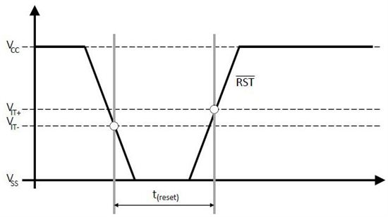
In the case of the MSP430F5342, this 2 µs would be the time from the moment the voltage at the reset input active low pin drops below the negative-going input threshold voltage until the moment the voltage rises above the positive-going input threshold voltage.

MSP430F534x Mixed Signal Microcontroller (Rev. B)  (PDF 771 KB)  17 Oct 2011 
Page 38 of 82

I created a timing diagram to illustrate how this would be measured.

For the MSP430F2011 reset input active low pin, what are the values for the negative-going input threshold voltage and positive-going input threshold voltage?  I don't see them defined in the data sheet.

MSP430F20x1, MSP430F20x2, MSP430F20x3 Mixed Signal Microcontroller (Rev. H)  (PDF 1841 KB)  02 Aug 2011 
Page 24 of 92

Please confirm if the timing diagram I inserted above for the MSP430F5342 also applies to the MSP430F2011.

  • Hi Jason,

    Your understanding is correct, for the newer parts like this 2xx, you ought to be able to use the Schmitt trigger input specs as a guide for your thresholds. Note that this is not really true for some of the older parts. When trying to determine the length of an external pulse to apply to the RST line you should also make sure to take into account the effect of RC circuit on your RST line and how this will affect your timing for achieving this 2us - this RC circuit values should follow the values noted in the user's guide and the hardware tools user's guide. Note also that you should use the worst case thresholds for your operating voltage, in this case use the min values since this is how far down you'll need to pull the line and you'll want to stay below these thresholds for at least 2us.

    Hope this helps clear things up, and I'll look into perhaps a way to make this clearer in the F2xx datasheet.

    Regards,

    Katie

  • Katie Enderle said:

    ... make sure to take into account the effect of RC circuit on your RST line and how this will affect your timing for achieving this 2us - this RC circuit values should follow the values noted in the user's guide and the hardware tools user's guide. 

    RC circuit values

    MSP430x2xx Family User's Guide (Rev. I)  (PDF 4314 KB)  24 Jan 2012
    Page 44 of 658

  • Katie Enderle said:

    I'll look into perhaps a way to make this clearer in the F2xx datasheet.

    Here are two changes that I propose:

    Change this text:

    Existing:
    Schmitt-Trigger Inputs (Ports P1 and P2)

    Proposed:
    Schmitt-Trigger Inputs (Ports P1, P2, RST_n/NMI/SBWTDIO)

    MSP430F20x1, MSP430F20x2, MSP430F20x3 Mixed Signal Microcontroller (Rev. H)  (PDF 1841 KB)  02 Aug 2011
    Page 24 of 92

    Add the timing diagram in the post above to the data sheet.

    MSP430F20x1, MSP430F20x2, MSP430F20x3 Mixed Signal Microcontroller (Rev. H)  (PDF 1841 KB)  02 Aug 2011
    Page 27 of 92

  • Katie Enderle said:
    I'll look into perhaps a way to make this clearer in the F2xx datasheet.

    The 5x datasheets could make use of the same update then :)

**Attention** This is a public forum