This thread has been locked.

If you have a related question, please click the "Ask a related question" button in the top right corner. The newly created question will be automatically linked to this question.

MSPM0G3519: RS485 Communication fail

Part Number: MSPM0G3519

Dear TI Experter

I am using the MSPM03915 to develop my design. I am designing a RS485 communication. The chain includes a master and three slaves. Three slaves are designed as the same hardware and software by using MSPM0G3519. The communicaion connection is shown as the picture.

image.png

My problem is shown as the following picture. The process can be describled as these steps:

  1. The system is started. All communcaitons are right. Master can send the data to three slaves, and three slaves can response the data to master in sequece.
  2. After some times, the error communication is created. In the picture, you can see all slaves receive the data from master right. Slave 1 sends its reponse to master. However, slave 2 and slave 3 only reveive the last four bytes of slave 1's response. 
  3. Master requires slave 2's data. However, slave 2 and slave 3 only receive the first five bytes of master's data. 
  4. After this time, only slave 1 can work. Slave 2 and 3 work like step 2 and step 3 wrong.

I also check the data in data bus. And, the data are right.
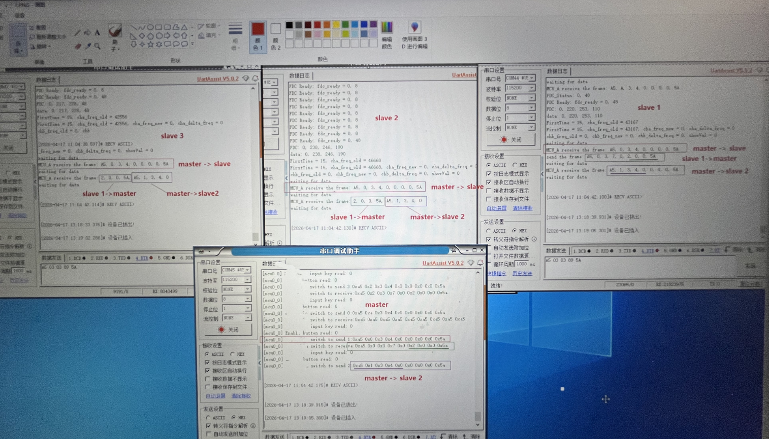
image.png

In my design, DMA polling mode is used to reveive and send UART data. And the communication is design as the process:

  1. Master send data 1 to three slaves for measuring some values.
  2. Master require slave 1's data, and slave 1 response the require.
  3. Master require slave 2's data, and slave 2 response the require.
  4. Master require slave 3's data, and slave 3 response the require.
  5. Go to step1.

Pls give your suggestion. Thanks.

  • DMA is fine on the transmit side but problematic for receive since any error can confuse it.

    I use DMA for RS485 transmit but the receive side uses interrupts and a state machine. And a timer, just in case.

  • Thanks for your answers. But, it does not seems to solve my problem. Can you share some experiences and demo based on my case?

  • Hi Dengkuan,

    It looks like some data missing during your UART communication.

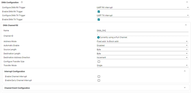
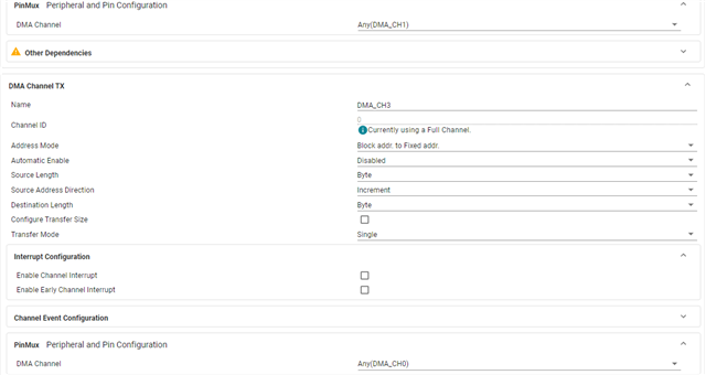
    How you configure UART TXFIFO and RXFIFO in your project, and what is the trigger level of FIFO in your setting?

  • Using DMA for receive is fragile and easily broken.

    When the master sends data to a slave, all of the slaves receive this data. One looks at it, sees that it is the target, and sends a reply.

    The other slaves look at the data, see that they aren't the target, and setup to receive another packet. But what if something (an interrupt perhaps) delays that setup? Then they miss one or more bytes from the packet. If their isn't a mechanism to resynchronize, the slaves never recover.

  • RX FIFO contains >=1 entry

    TX FIFO contains 1 entry

  • If I do not use DMA, can you share some examples to handle the case?

  • I could but the Insert:code editor feature isn't working for me.

  • Hi David,

    You can try to zip the code and put it as drag it into the chat window.

    Hi Dengkuan,

    As PengFei mentioned it is better to show more configure details to us, better to provide a simple demo code that can reproduce the issue here.

    One more question from myside is have you try to use interrupts to handle the massage instead of DMA? 

  • Hi Gary and Fengfei

    You can refer to these information.

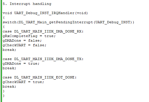
    For handling UART and DMA:

    1. The structure defination:

    {
    .uartBaseAddr = UART_Debug_INST,
    .txDataAddr = &UART_Debug_INST->TXDATA,
    .rxDataAddr = &UART_Debug_INST->RXDATA,

    .DMATxChannel_ID = DMA_CH3_CHAN_ID,
    .DMARxChannel_ID = DMA_CH2_CHAN_ID,
    .DMARxsize = RS485_RX_FRAME_SIZE,
    .DMATxChannel_InterruptSignal = DMA_CPU_INT_RIS_DMACH0_MASK,
    .DMARxChannel_InterruptSignal = DMA_CPU_INT_RIS_DMACH1_MASK,
    .irqn = UART_Debug_INST_INT_IRQN,

    }

    2. The initialization of UART:

    void UART_Init(UART_index const uartIndex)
    {

    DL_DMA_clearInterruptStatus(DMA, UARTInst[uartIndex].DMATxChannel_InterruptSignal);
    DL_DMA_clearInterruptStatus(DMA, UARTInst[uartIndex].DMARxChannel_InterruptSignal);
    if(UARTInst[uartIndex].irqn == UART_Debug_INST_INT_IRQN)
    {
    NVIC_EnableIRQ(UARTInst[uartIndex].irqn);
    }


    UART_RX_DMA_cfg(uartIndex);
    }

  • Hi Dengkuang,

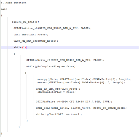
    Little confusing about the while loop code

    I do not see where to check if the byte is command byte or address byte. And after you configure the RX DMA , you can make the device go into low power mode or check some flag to wait the command from host side. I do not see the wait RX data code before send data.

  • You can try to zip the code and put it as drag it into the chat window.

    /*  USCI receive interrupt handler
    
      Note that USCI_A0 and USCI_B0 share one vector.
    
      This is a bit more complicated since it handles receiving a complete 
      packet.
    
      The receive state machine:
    
      The state machine is a simple progression from one state to the next.
      Errors (timeout) result in a return to state zero.
    
      State     waiting for?
        0         nothing
        1         looking for SYNC character
        2         Reads up to length byte
        3         Reads remainder of packet
    
        Once a complete packet is recevied, an event is added to the queue. The
        main loop is then awakened so that it can examine the packet.
    */
     
    __attribute__((interrupt(USCI_A1_VECTOR))) void rxISR(void)
    {
      static int i, count;
      int c;
    
      switch(UCA1IV)
        {
        case USCI_UART_UCRXIFG:
          c = UCA1RXBUF;   // get the received character
          switch(rx_state)
            {
            case 0:     // Drop all received characters in state 0
              break;         
            case 1:     // scanning for SYNC character
              if(c == PSYNC)
                {
    	      TA2CCR1 = TA2R + CHAR_TIMEOUT;  // reset timeout timer
                  i = 0;
                  rx_state = 2;
                }
              break;
            case 2:
              TA2CCR1 = TA2R + CHAR_TIMEOUT;  // reset timeout timer
              RPacketBuf[i++] = c;
              if(i == 3)         // this should be the count of bytes in the data packet
    	                {
                  count = c+5;       // Don't forget the header and CRC
                  rx_state = 3;
                }
              break;
            case 3:
              TA2CCR1 = TA2R + CHAR_TIMEOUT;  // reset timeout timer
              if(i < BUFSIZE)     // Drop all characters that don't fit buffer
                RPacketBuf[i++] = c;
              if(i >= count)
                {
                  rx_state = 0;
                  recv_flag = RECV_OK;
                  TA2CCTL1 &= ~CCIE;  // disable compare interrupt
    	      WAKEUP;
                }
              break;
            default:
              rx_state = 0;
              recv_flag = RECV_IDLE;
            }
          break;
        case USCI_UART_UCTXIFG:
          break;
        case USCI_UART_UCSTTIFG:
          break;
        case USCI_UART_UCTXCPTIFG:
          if(UCA1IFG & UCTXIFG)
    	{
    	  LED2_OFF;
    	  P3OUT &= ~0x10;          // disable transmitter
    	}
          break;
        }
    }

    I tried again and this time I didn't end up with a blank field.

    This code is for a MSP430 so is not directly applicable to the MSPM0. But I am not of the current school of not commenting code so it should be easy to follow.

    The main code is responsible for verifying that the packet checksum and address is correct.

  • Hi Gary,

    I just post the main while and do not include everything. I do not want the device to go into low power mode. For checking some flag, can you give some detail information? memcpy is used to copy the DMA data to the data structure which needs to be processed. Of course, I did not write the detail information.

    In addition, it is hope that we can discuss this by face to face because it is very urgent. Thanks.

  • Hi Dengkuan,

    Sorry for late reply since I'm out of office last week. As we discussed offline, currently MCU Uart Rx interrupt could be well triggered.

    The current problem is there is still byte missing problem during communication. I recommend to debug in below way:

    •  Use a large buffer to record all the received data from UART, and compare it with UART waveform.
    • Check UART waveform and check the timing between CTS and UART signal.
    • Check whether their is disable global interrupt code in your application.

    Best Regards,

    Pengfei

**Attention** This is a public forum