Part Number: MSP430F67771A
My product uses two MSP430F67771A which need to stay synchronised. So, I have a single 32768 Hz crystal oscillator providing a reference clock to the XIN pins. I am using the FLL, with FLLD = 1 and FLLN = 488. So, I expect the DCO frequency to be 32768 * 488 = 15.99 MHz.
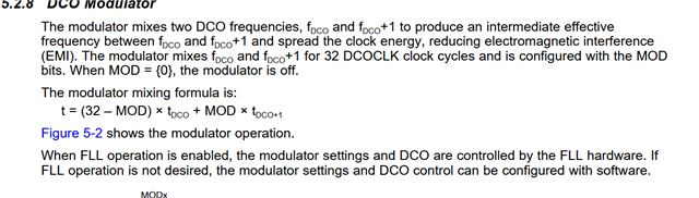
The DCO frequencies are very close to 15.99 MHz; however the two devices do not stay synchronised. If I count the number of DCO cycles and the number of XIN cycles over a long period of time, I find that the ratio is not exactly 488 (it's about 488.4 on the device measured). This is surprising, because the block diagram (slau390f fig 1.1) shows a 10 bit frequency integrator, which is incremented by the reference clock and decremented by the divided DCO clock. If the loop contained an integrator, the long term frequency ratio would be exactly FLLN / FLLD. So, I suspect the diagram is not an accurate representation of the FLL implementation.
1] Is it possible to configure the FLL so that it maintains the exact integer long term frequency ratio?
2] If not, then would it help to use a higher external reference frequency (eg. 4 MHz, FLLD = 1, FLLN = 4)?
3] Please provide details of how the FLL loop filter works.