This thread has been locked.

If you have a related question, please click the "Ask a related question" button in the top right corner. The newly created question will be automatically linked to this question.

MSP430FR6007: issue regarding configuration of SPI

Part Number: MSP430FR6007
Other Parts Discussed in Thread: MSP430WARE

I am using the MSP430FR6007IPZ microcontroller and configuring SPI using the UCA2CTLW0 register. However, I am not getting any SPI signals on the oscilloscope (no clock or data activity).

I have checked the hardware connections and SPI pin configuration, but I am still unable to identify the issue.

Could someone please review my SPI initialization code and suggest what might be wrong? Any guidance on properly configuring SPI on the MSP430FR6007 would be greatly appreciated.

Here is my SPI configuration code:

 Init_SPI(void)
{
    UCA2CTLW0 = UCSWRST;      // Hold eUSCI in reset

       // SPI pins
       P5SEL0 |= BIT0 | BIT1 | BIT2;
       P5SEL1 &= ~(BIT0 | BIT1 | BIT2);

       // CS pin
       P5OUT |=BIT3;
       P5DIR |= BIT3;


       // CLR pin
       P5OUT |= BIT4;
       P5DIR |= BIT4;

      UCA2CTLW0 |= UCMST | UCSYNC | UCCKPL | UCMSB | UCMODE_1 |           UCSTEM;

      UCA2CTLW0|=UCSSEL__SMCLK;

      UCA2BRW = 0x20;

      UCA2CTLW0 &= ~UCSWRST;      // Enable SPI

}

smclk = 8 MHz

SMCLK Frequency: (e.g., 8 MHz)

  • You have selected a 4 pin SPI mode. Given that you didn't configure a pin for the STE signal, have an explicit CS pin, and the usual misunderstanding of the 4 pin mode, you probably want the 3 pin mode.

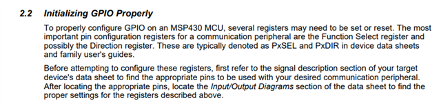
    But the main problem is the port select bits. You need SEL0 = 0 and SEL1 = 1. (Table 9-31)

  • Thank you for your response, David Schultz.

    After reviewing the datasheet, I updated my code according to your suggestions. I now see some activity on the oscilloscope, which is progress compared to before. However, the SPI waveform does not appear to be correct or stable, so I believe there may still be a configuration issue.

    I also have a question regarding pin multiplexing on the MSP430FR6007.

    I noticed that the same physical pins can be assigned to multiple peripheral functions, such as SPI and UART. For example, a pin may support both UCA2 SPI signals and UART TX/RX functions. Could you please explain how to determine which peripheral function is active? Specifically, how do the PSEL0 and PSEL1 register settings select between SPI, UART, GPIO, and other alternate functions?

    Additionally, since I am now seeing some response on the oscilloscope but not the expected SPI waveform, could you suggest what I should check next to verify that the SPI configuration is correct?

    I would appreciate any clarification on how the pin multiplexing mechanism works and any guidance on troubleshooting the SPI signal.

    Thank you for your help.

    UCA2CTLW0 = UCSWRST; // Hold eUSCI in reset


    // P5DIR |= BIT0; // CLK
    // P5DIR |= BIT2; // MOSI
    // P5DIR &= ~BIT1; // MISO
    // SPI pins

    P5SEL0 &= ~(BIT0 | BIT1 | BIT2);
    P5SEL1 |= BIT0 | BIT1 | BIT2;

    // CS pin
    P5OUT |=BIT3;
    P5DIR |= BIT3;


    // CLR pin
    P5OUT |= BIT4;
    P5DIR |= BIT4;

    UCA2CTLW0 = UCSWRST; // **Put state machine in reset**

    UCA2CTLW0 |= UCMST | UCSYNC | UCCKPL | UCMSB | UCMODE_0;
    UCA2CTLW0 |= UCSSEL__SMCLK; //
    // UCB1BRW = 0x20;
    UCA2BR0 = 0x02; //
    UCA2BR1 = 0; //
    // UCA0MCTLW = 0; // No modulation

    UCA2CTLW0 &= ~UCSWRST; 

  • With not even a description of the unexpected waveform to go on, I have nothing. Actual code sending data to the SPI port and a picture of the output would help.

    Pin configuration is well covered in the pin diagram section of the data sheet.

  • Hi,

    I believe we have provided several SPI demo code in our MSP430 SDK  in the following folder, you can take a quick look and compare your code to ours to see if there is any potential issue.

    "C:\ti\SDK\MSP430Ware_3_80_14_01\examples\devices\MSP430FR5xx_6xx\MSP430FR60x7_MSP430FR60x5_Code_Examples\C"

    Best Regards,
    Peter

  • ok  but i my question ,i noticed that the same physical pins can be assigned to multiple peripheral functions, such as SPI and UART. For example, a pin may support both UCA2 SPI signals and UART TX/RX functions. Could you please explain how to determine which peripheral function is active? Specifically, how do the PSEL0 and PSEL1 register settings select between SPI, UART, GPIO, and other alternate functions? 

    e.g pin spi selection   psel0=0 , psel1=1 then what for uart ?

  • Hi ,

    Thank you for your reply.

    I reviewed the demo code, but it does not include examples for all eUSCI modules (such as UCA1, UCA2, UCB0, UCB1, etc.), so it is difficult to determine the correct configuration for a specific module based solely on the demo.

    with the same PSEL0 and PSEL1 settings.

    In this case, how can I determine which protocol is active on the pin? Will the pin function as SPI (SIMO) or UART (TXD)? Is the active function determined by the configuration of the UCA1CTLW0 register (SPI mode vs UART mode), or is there another mechanism involved?

    I would appreciate some clarification on how the MSP430 selects between SPI and UART functionality when multiple peripheral functions share the same pin.

    Thank you for your assistance.

    I also have one question regarding pin multiplexing. For example, in the datasheet, a pin may be listed as:

    UCA1SIMO / UCA1TXD

  • e.g pin spi selection   psel0=0 , psel1=1 then what for uart ?

    The pin doesn't know or care. Module configuration determines if it is UART or SPI.

**Attention** This is a public forum