Part Number: MSPM0L2228
I am having trouble enabling the VREF for COMP module.
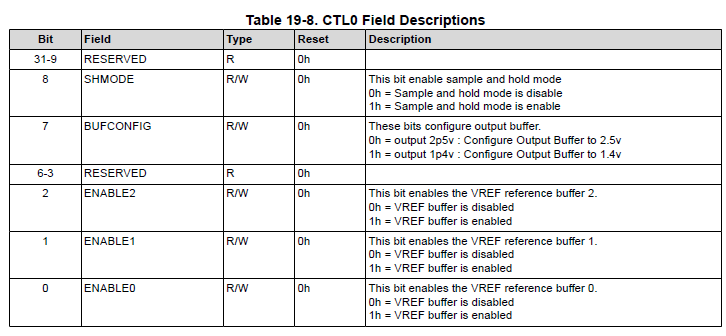
Can someone help clarify the fields: ENABLE0 Vs ENABLE1 Vs. ENABLE2?
Below is the table from slau847f 
This thread has been locked.
If you have a related question, please click the "Ask a related question" button in the top right corner. The newly created question will be automatically linked to this question.
Part Number: MSPM0L2228
I am having trouble enabling the VREF for COMP module.
Can someone help clarify the fields: ENABLE0 Vs ENABLE1 Vs. ENABLE2?
Below is the table from slau847f 
Hi,
The Enable bits can be described as follows:
The following is a capture from the hw_vref.h source file in the SDK:
Best Regards,
Brian
Brian Lee , I found the #define definitions you shared. While trying to verify register settings by using the REGISTERS view, I noticed the ADC bit is missing. Can you help confirm or advise where it is located?
I used this code line in main():
// DISABLE the comparator to unlock the hardware registers
DL_COMP_disable(COMP_INST);
VREF->CTL0 |= (VREF_CTL0_COMP_VREF_ENABLE_ENABLE | VREF_CTL0_ADC_VREF_ENABLE_ENABLE);
// Re-enable the comparator
DL_COMP_enable(COMP_INST);
Auto generated code:
static const DL_VREF_ClockConfig gVREFClockConfig = {
.clockSel = DL_VREF_CLOCK_LFCLK,
.divideRatio = DL_VREF_CLOCK_DIVIDE_1,
};
static const DL_VREF_Config gVREFConfig = {
.vrefEnable = DL_VREF_ENABLE_ENABLE,
.bufConfig = DL_VREF_BUFCONFIG_OUTPUT_2_5V,
.shModeEnable = DL_VREF_SHMODE_DISABLE,
.holdCycleCount = DL_VREF_HOLD_MIN,
.shCycleCount = DL_VREF_SH_MIN,
};
SYSCONFIG_WEAK void SYSCFG_DL_VREF_init(void) {
DL_VREF_setClockConfig(VREF,
(DL_VREF_ClockConfig *) &gVREFClockConfig);
DL_VREF_configReference(VREF,
(DL_VREF_Config *) &gVREFConfig);
delay_cycles(VREF_READY_DELAY);
}
/* COMP Initialization */
static const DL_COMP_Config gCOMPConfig = {
.channelEnable = DL_COMP_ENABLE_CHANNEL_NEG,
.mode = DL_COMP_MODE_ULP,
.negChannel = DL_COMP_IMSEL_CHANNEL_0,
.posChannel = DL_COMP_IPSEL_CHANNEL_0,
.hysteresis = DL_COMP_HYSTERESIS_NONE,
.polarity = DL_COMP_POLARITY_NON_INV
};
static const DL_COMP_RefVoltageConfig gCOMPVRefConfig = {
.mode = DL_COMP_REF_MODE_STATIC,
.source = DL_COMP_REF_SOURCE_INT_VREF_DAC,
.terminalSelect = DL_COMP_REF_TERMINAL_SELECT_POS,
.controlSelect = DL_COMP_DAC_CONTROL_SW,
.inputSelect = DL_COMP_DAC_INPUT_DACCODE0
};
SYSCONFIG_WEAK void SYSCFG_DL_COMP_init(void)
{
DL_COMP_init(COMP_INST, (DL_COMP_Config *) &gCOMPConfig);
DL_COMP_refVoltageInit(COMP_INST, (DL_COMP_RefVoltageConfig *) &gCOMPVRefConfig);
DL_COMP_setDACCode0(COMP_INST, COMP_DACCODE0);
DL_COMP_enableInterrupt(COMP_INST, (DL_COMP_INTERRUPT_OUTPUT_EDGE
| DL_COMP_INTERRUPT_OUTPUT_EDGE_INV));
DL_COMP_enable(COMP_INST);
}

Hi,
The available bits for the VREF CTL0 register are device dependent. In the case of MSPM0L2228, CTRL0[0] enables the external cap based VREF for the ADC and COMP as well as the internal cap-less VREF for ADC. CTRL0[1] enabled the internal cap-less VREF for COMP.
Sorry for the confusion the TRM descriptions may have caused. This has been reported and changes to our documentation and SDK will be made to better reflect this.
Best Regards,
Brian
Brian Lee , can you clarify more:
In the case of MSPM0L2228, CTRL0[0] enables the external cap based VREF for the ADC and COMP as well as the internal cap-less VREF for ADC. CTRL0[1] enabled the internal cap-less VREF for COMP.
This has been reported and changes to our documentation and SDK will be made to better reflect this.
/* VREF_CTL0[ENABLE] Bits */ #define VREF_CTL0_ENABLE_DISABLE VREF_CTL0_ENABLE0_DISABLE /* !< VREF is disabled */ #define VREF_CTL0_ENABLE_ENABLE VREF_CTL0_ENABLE0_ENABLE /* !< VREF is enabled */ /* VREF_CTL0[COMP_VREF_ENABLE] Bits */ #define VREF_CTL0_COMP_VREF_ENABLE_DISABLE VREF_CTL0_ENABLE1_DISABLE /* !< COMP VREF is disabled */ #define VREF_CTL0_COMP_VREF_ENABLE_ENABLE VREF_CTL0_ENABLE1_ENABLE /* !< COMP VREF is enabled */ /* VREF_CTL0[ADC_VREF_ENABLE] Bits */ #define VREF_CTL0_ADC_VREF_ENABLE_DISABLE VREF_CTL0_ENABLE2_DISABLE /* !< ADC VREF is disabled */ #define VREF_CTL0_ADC_VREF_ENABLE_ENABLE VREF_CTL0_ENABLE2_ENABLE /* !< ADC VREF is enabled */
Hi,
For this device, Enable2 should be a reserved bit and should not show up in the register view. To see all bitfields, reserved and defined, you can connect to the CORTEX_M0P with the debugger and open the memory viewer:
Our SDK currently gates this device from enabling the internal VREF to the COMP, but I am still waiting on clarity as to why this is:
In the VREF module, checking the box that enables the internal VREF to the COMP generates a call to the above API. This would lead to an error with the ti_msp_dl_config.c file explaining why your initial project would not build properly.
Best Regards,
Brian
Hi,
ENABLE2 is not reserved in the TRM, but it should not be defined for this device. There are internal teaks discussing how this should be handled going forward, but I cannot currently provide a timeline for when it will be clarified. I'm sorry for the confusion this has caused.
Best Regards,
Brian
**Attention** This is a public forum