This thread has been locked.

If you have a related question, please click the "Ask a related question" button in the top right corner. The newly created question will be automatically linked to this question.

STACKING 2 OR MORE MCU'S

HI ALL,

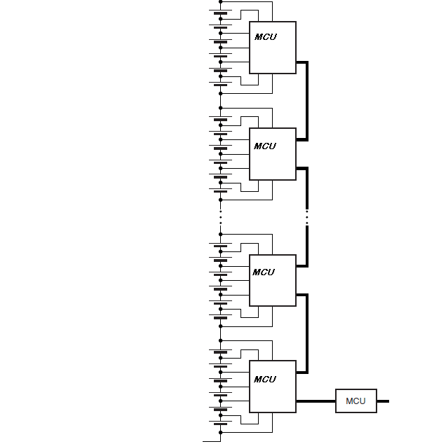
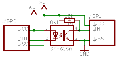
I WAS READING 1 F D POST http://e2e.ti.com/support/microcontrollers/msp43016-bit_ultra-low_power_mcus/f/166/t/144376.aspx#521161 & HAVE SAME QUESTION HOW TO STACK 2 MCU'S. HOW DOES IT AFFECTS THE CIRCUIT WHEN GND OF 1 MCU IS CONNECTED TO VDD OF LOWER MCU & TO SOLVE THE PROBLEM. 

HERE AN EXAMPLE

  • The simplest way to do this is to use resistive voltage dividers for both the battery monitoring and the data communication inputs.

    The data communication is processed by the ADC and then decoded in software. 

    Peter

  •  Hi, in the other post I proposed a network that draw no current from cell other than during active communication, you have to complete with autoconfiguration logic to do recognition of cell position. In that basic design proposal I removed it.

     Raising cell voltage to a higher voltage is no problem to that circuit till VDS can withstand two cell voltage but resistive divider to measure cell voltage draw a lot of current and the cost of an entry level MSP discourage using more than 1 cell per MSP, precision resistor cost more than an extra MSP.

     So why multicell on single MSP? This design require galvanic isolation between cell group and an ISO chip can be more adeguate than my proposal.

     Regards

     Roberto

  • HI, CKT GIVEN BY U IS NT CLEAR, CAN U PLZ ATTACH IT, INSTEAD OF INSERTING IMAGE.

    I HAVE CHECKED IT IN MANY CKTS, STACKING UP 2 MCU'S.. THEY TALK OF SOME REVERSE BIASED DIODES. THAT'S ALL I KNOW. I DON'T KNOW EXACTLY HOW IT HAPPENS.

  • help on this

  • Aamir Ali said:
    HOW DOES IT AFFECTS THE CIRCUIT WHEN GND OF 1 MCU IS CONNECTED TO VDD OF LOWER MCU & TO SOLVE THE PROBLEM. 

    TH eproblem is the communication between the MCUs. Each one for itself won't have a problem. But if you want to pass data from the upper to the lower, teh 'low' will be the other ones 'high' and the 'high' will be far above teh other ones VCC.

    The first obvious and simplest solution is using an optocoupler.

    You'll likely need an additional series resistor on the diode input, to limit the current. While the drawn pullup resistor might be replaced with the MSPs internal pullup, if available.
    The connection may be SPI or UART, but not I2C. And can go in both directions if needed.

  •  Please can you reword this in English so I can read what you wrote?

     One post carry image file so you can download it.

     Example design is modular draw no energy than when communicating, can be extended as you like, design is best fitted if just one or two cell where used otherwise precision resistor wasted energy and complexity discourage this in place of voltage scaling network.

     Regards.

  • Hi Jens,

    I got your point how to establish communication between two MCU.

    But if stack two McU, will they work fine, if gnd of one mcu is connected to Vcc of lower McU or some isolator is required like reverse biased diode.

    Hi Roberto,

    Image post by you is not clear. Instead of pasting it, can you attach the file, so that I an download it.

  • any help abt dis.............

  • Hi,

    There are few options to establish such DC isolated MCU2MCU communication by capacitors cuppling.

    The implemented design subjected to the data rate, sync/asinc, uni/bidirection, Vhigh-Vlow ...

    BR,

    Yoav Shoham

  • I got point how to establish communication as suggested by Jens.

    Now my question is if I stack two MCU, will it create problem in their operation or they will fine or some extra ckt has to be added b/w two.

  • Aamir Ali said:
    Now my question is if I stack two MCU, will it create problem in their operation or they will fine or some extra ckt has to be added b/w two.

    If there is only one single direct connection between the two MCUs, there is no problem. So yes, you can connect the same voltage level as VCC to one and as GND to the other MSP. However, no other pins may be directly connected (hence the opto coupler).
    If this is the only direct connected point, then the two will behave as if their supply voltage were totally independent.
    Voltage is relative.

    What is the voltage between a 9V and a 1.5V battery? It is indeterminable as long as there is no connection at all.  If there is a connection, then it depends on where this conneciton is: if you connect 1.5V and 9V positive side, then the answer is 0V (but -7.5V between the two negative sides) If you connect 9V negative to 1.5V positive, the answer is 9V (and 10.5 to the 1.5V negative).

     You see, you always need two connections. One to set the relation, and one to measure. If your MSPs ony touch at one point, there will be a measurable dangerous voltage between any of their other pins, but as long as these do nout touch, you don't have to care.

**Attention** This is a public forum