This thread has been locked.
If you have a related question, please click the "Ask a related question" button in the top right corner. The newly created question will be automatically linked to this question.
How stable, that is, how repeatable, is the MSP43 internal temperature sensor?
I'm getting some unexpectedly high readings from the internal temperature sensor on my chip via ADC10. Since I don't _really_ think my chip is occasionally running hotter than boiling water (144degC??!!), I thought I'd ask for some advice.
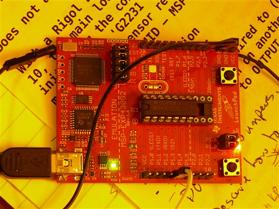
I have code running on a LaunchPad/'G2231 that does three things:
1) Blinks an LED with a "220" ohm resistor on P1.4,
2) Monitors/debounces the LP S2 button, and
3) Samples the internal temperature sensor (ADC10 channel 1010b).
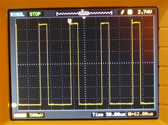
The LED is driven with a "manually-generated" PWM signal timed by Timer_A0 (4000 interrupts/sec). The pulse rate is 2 Hz -- 2000 Timer_A ticks -- and initially the PWM "ON" period is 10 Timer_A ticks, for a 10/2000 or 0.5% duty cycle.
Each time S2 is pressed, the ON period is increased by 10 more ticks.
Meanwhile, in the background, ADC10 is sampling the internal temperature sensor watching for signs of heating up, that is, an ADC10(1.5Vref) value of 757, which ought to represent 35degC. If this happens, it shuts off the external LED and turns on LP LED2 (green) to signal a problem.
So far, so good. One might assume that a "too hot" condition would never be achieved, since the chip is only powering itself, Timer_A0, ADC10, and the external LED.
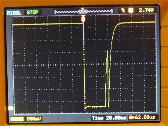
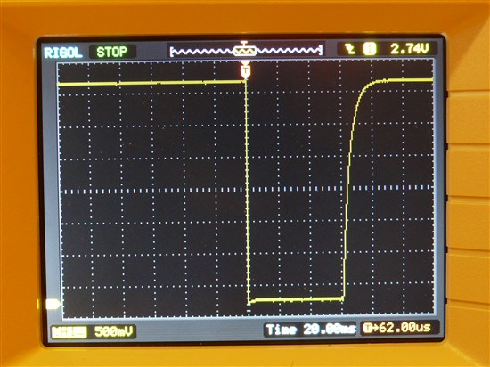
And so it seems... Running under 'mspdebug' and periodically stopping to check the ON tick counts and current temperature, I gradually increase the pulse width to 200 (of 2000) ticks and all is well: the LED flash is _slightly_ longer, and the internal temperature stays in the range 0x02d6-0x02da (726-730, or 22-24degC).
Then, somewhere between 250 ticks and 500 ticks, Something Happens: ADC10 unexpectedly reports a value exceeding not just the 757 "trip point" but well above it, in several cases reporting values of 0x3ff (144degC).
I scanned the E2E postings and found several reports of an internal temperature sensor reporting higher-than-expected values, but none quite _this_ extreme.
Assuming that this isn't simply some kind of coding or setup error (perhaps a large assumption <grin!>), that leaves -- what? -- the sensor, the ADC, and the internal 1.5V reference.
Can anyone offer any suggestions as to why I might be seeing this effect?
A few details:
The chip is a 'G2231.
The LP Vcc is 3.57V. When the LED+R is connected between Vcc and Gnd, the voltage drop across R (measured at 218 ohms) is 0.69V, indicating a current of about 3.2mA, well within the pin's spec.
Timer_A:
TACCR0: 0x00f9 "250"
TACTL: 0x0210 TASSEL_2|ID_0|MC_1
TACCTL0: 0x0010 OUTMOD_0|CCIE
ADC10:
ADC10CTL0: 0x38b8 SREF_1|SHT_3|MSC|REFON|ADC10ON|ADC10IE
ADC10CTL1: 0xa07c INCH_10|SHS_0|ADC10DIV_3|ADC10SSEL_3|CONSEQ_2
ADC10AE0: not used
Frank McKenney
--
It has often been said that we have but one life to live; that is
nonsense. If one reads fiction he or she can live a thousand
lives, in many parts of the world or in outer space. One can
cross a desert, climb the Himalayas, or experience the agony of
defeat, the triumph of victory, the pangs of starvation, or the
choking thirst of the desert, all while safely at home.
-- Louis L'Amour / The Sackett Companion
--
Is the above problem repeatable in a stripped down code ?
Can you post the code ?
ADC output of $3FF is full scale. Check your Vref enable and settling time
Peter
Hi Frank,
first of all - a good idea to point this out would be a test, where you only use your routine for reading the temperature value without the cpu doing anything else and see if problem persists.
When you use the internal reference generator you should keep in mind that it needs some time to settle to a stable value. For value line devices the settle time is about 30us when REFON is set from 0 to 1. Your reading 0x03FF is a full scale reading which _could_ mean that the reference is not stable yet (there may transients on Vref while settling).
Just for completeness, I looked info the familiy guide and 30us are indeed correct, take a look here:
http://www.ti.com/lit/ug/slau144i/slau144i.pdf
Chapter 22.2.3 - Voltage Reference Generator and
Chapter 22.2.8 Temperature Sensor
The later one also points out that sampling time for the sensor must be >30us. How fast is your device running? Maybe you are under the allowed minimum (did not recalculate it right now :-)
Peter,
Thanks for replying. Those are all good questions.
Peter Dvorak said:Is the above problem repeatable in a stripped down code ?
This would be a Very Useful Thing (and one I had forgotten about), but I have not yet reached that point in my "research".
Peter Dvorak said:Can you post the code ?
There are no legal restrictions, but at present the code consists of roughly 400 lines of code and comments. As I noted in my initial post, it uses Timer_A and ADC10, so trimming the code (including the two interrupt handlers) may not be not a simple task.
Peter Dvorak said:ADC output of $3FF is full scale. Check your Vref enable and settling time
REFON is being set, if that's what you're asking; see my initial post.
As for the delay, it's sloppy but should be sufficient: <grin>
// Pause briefly to allow Vref to settle
uint16_t adc10_delay = ((50*CPUF)/1000000L); // 50usec delay
while ( adc10_delay > 0 ) {
adc10_delay--;
}
Also, the problem does not show up until at least 20 full seconds after a restart, since it takes me that long to move my hands from the keyboard to the LaunchPad and start pressing the button. Since ADC10 is currently running around 3k samples/sec, this would be at least 60k samples since the restart.
Frank
Hello, Jan.
Thank you for joining in.
Jan Kesten said:first of all - a good idea to point this out would be a test, where you only use your routine for reading the temperature value without the cpu doing anything else and see if problem persists.
I could do that, but the "hiccup" does not seem to occur when I leave the LaunchPad alone, even after ten or twenty minutes. It appears to only occur after I press S2 multiple times, which also increases the "pulse width".
Just to make things more interesting, the "hiccup" occurs at varying pulse widths, from as short as 40/2000 to as wide as 1000/2000.
Jan Kesten said:When you use the internal reference generator you should keep in mind that it needs some time to settle to a stable value. For value line devices the settle time is about 30us when REFON is set from 0 to 1. Your reading 0x03FF is a full scale reading which _could_ mean that the reference is not stable yet (there may transients on Vref while settling).
Yes, I believe I'm accounting for this. See my reply to Peter.
Jan Kesten said:Just for completeness, I looked info the familiy guide and 30us are indeed correct, take a look here:
http://www.ti.com/lit/ug/slau144i/slau144i.pdf
Chapter 22.2.3 - Voltage Reference Generator and
Chapter 22.2.8 Temperature Sensor
The later one also points out that sampling time for the sensor must be >30us. How fast is your device running? Maybe you are under the allowed minimum (did not recalculate it right now :-)
What, check my code? <grin!>
ADC10CTL0: ADC10SHT_3 (sample&hold=64 * ADC10CLK) )
ADC10CTL1: ADC10SSEL_3|ADC10DIV_3 (use SMCLK, /4)
Running at 1MHz, that makes ADC10CLK 1000000/4 or 250kHz, and the total time per sample (64+13)/250k or 308usec... roughly 3.2k samples/sec.
Since my initial post I have added a trace buffer to see how abrupt the "temperature change" is. Here's a sample dump from the debugger:
(mspdebug) md pulse_on_ticks
00204: 90 01 400 decimal (20% duty)
(mspdebug) md final_temp
00214: 76 03 886 decimal
(mspdebug) md tt_index
00218: 02 00 tt_buffer[2] is the next entry
(mspdebug) md tt_buffer (last 16 ADC10 temperature values)
0021c: d2 02 76 03 d2 02 d3 02 d2 02 d3 02 d2 02 d3 02
0022c: d1 02 d2 02 d2 02 d3 02 d2 02 d2 02 d2 02 d2 02
In other words, the raw "temperature" value reported stays steady around 721-723 (0x02d1-02d3), and then, within 1/3200th of a second, rises to 886.
Using the formula Tc = (( ADC10 * 0.413) - 277.75 ), the jump is from 20.0-20.8degC to 88.2degC.
I haven't tried capturing samples following a "bad" reading, but I'd guess that they would be close to 20degC.
Frank
A minor update:
- I have succeeded in triggering an "odd" reading without using the debugger. (I can tell this has happened because when it occurs my code turns LP LED1 on and starts blinking LP LED2.)
- I have also reproduced it without the debugger and with no external LED attached.
This leaves Timer_A and its interrupt handler, and ADC10 and its interrupt handler. And S2. And the 'G2231. And the LaunchPad board itself. (And three other things I haven't even thought of. <grin!>)
Frank
P.S. Just for reference, the current moon phase is "just past full" (Waning Gibbous). <grin!>
Some comments on "timing" (not sure if these are the cause of your problem):
1:
The data sheet for the MSP430G2231 defines the fADC10CLK parameter with a minimum of 0.45 MHz. i.e. the ADC10CLK is less than the minimum specified for the ADC10 operation.Frank McKenney said:Running at 1MHz, that makes ADC10CLK 1000000/4 or 250kHz
2:
Frank McKenney said:// Pause briefly to allow Vref to settle
uint16_t adc10_delay = ((50*CPUF)/1000000L); // 50usec delay
while ( adc10_delay > 0 ) {
adc10_delay--;
}
Unless adc10_delay is declared as volatile the compiler optimization may remove the loop. Better to use the __delay_cycles compiler intrinsic.
The timings should be ok indeed - looks good. So there are two things that are strange, first the reading of full-scale values and the jumps in the series of consecutive.
Your very first sentence makes me think of an esd/emi issue. While it is simple to average the value readings to get your problem fixed the cause is interesting. If I have some spare time, I'll try with a simple test loop for myself tomorrow ;-)
Hi, Chester.
Thank you for your comments.
Chester Gillon said:1.The data sheet for the MSP430G2231 defines the fADC10CLK parameter with a minimum of 0.45 MHz. i.e. the ADC10CLK is less than the minimum specified for the ADC10 operation.[/quote]Running at 1MHz, that makes ADC10CLK 1000000/4 or 250kHzUm. "...minimum of 0.45 MHz..." ...
You mean the one mentioned in the comments for my ADC10_Init() routine:
//* Note 1: Per the MSP430G2x31 datasheet (under 10-Bit ADC Timing
//* Parameters), ADC10CLK must be 0.45-6.3 MHz (0.45-1.5 MHz
//* if ADC10SR=1). Since we're running at 1 MHz, that pretty
//* much limits ADC10DIVx to 0 and 1 (SMCLK/1, SMCLK/2).
just above where I was specifying ADC10DIV_3 ?"Sighted foot, sank same."
Thank you for pointing this out.
Chester Gillon said:2.// Pause briefly to allow Vref to settle
uint16_t adc10_delay = ((50*CPUF)/1000000L); // 50usec delay
while ( adc10_delay > 0 ) {
adc10_delay--;
}Unless adc10_delay is declared as volatile the compiler optimization may remove the loop. Better to use the __delay_cycles compiler intrinsic.[/quote]
Yes. I don't think this was the problem, but you're right -- it might nail me next time. Here's a rough equivalent from the mspgcc manual that now resides in my code:
//*--------------------------------------------------------------
//* brief_pause(n) - Delay roughly n*3 cycles (see mspgcc manual)
//*--------------------------------------------------------------
static void __inline__ brief_pause(register unsigned int n) {
__asm__ __volatile__ (
"1: \n"
" dec %[n] \n"
" jne 1b \n"
: [n] "+r"(n));
}The problem still occurs, but I appreciate your pointing out to me these problems with my code.
Frank
P.S. Sorry about the mangled quoting. I suspect that there's some "invisible" HTML in there that's confusing the editor.
Jan Kesten said:The timings should be ok indeed - looks good. So there are two things that are strange, first the reading of full-scale values and the jumps in the series of consecutive.
I have an update on the sequencing. I added code which continues tracing the next 8 temperature sensor values after an anomalous one is seen. Here is one such sequence, with the 7 values preceeding the anomalous reading, the odd value itself, and the next 8 values read from ADC10:
Hex: 2d5, 2d3, 2d4, 2d5, 2d5, 2d4, 2d5, << 354 >>, 2d4, 2d5, 2d4, 2d4, 2d5, 2d5, 2d4, 2d4
ADC10CLK is now 500kHz, and I'm sampling at roughly 6.5k samples/sec.
Jan Kesten said:Your very first sentence makes me think of an esd/emi issue.
Um... which first sentence was that? (I may want to have it bronzed. <grin!>)
Jan Kesten said:While it is simple to average the value readings to get your problem fixed the cause is interesting. If I have some spare time, I'll try with a simple test loop for myself tomorrow ;-)
If I learn anything more I'll post it here.
Thank you again for your assistance.
Frank
--
Perfect as the wing of a bird may be, it will never enable the
bird to fly if unsupported by the air. Facts are the air of
science. Without them a man of science can never rise.
-- Ivan Pavlov
--
Frank McKenney said:This leaves Timer_A and its interrupt handler, and ADC10 and its interrupt handler.
Frank do you really need the ADC ISR?
Do you use low power modes?
Can you see bad ADC readings from Vmid (VCC divider at channel 11) ?
Peter
Hi, Peter.
It looks like, whatever the problem is, it isn't specific to the first LaunchPad board I was using. I loaded the code onto a second LP (with a different 'G2231) and was able to reproduce the problem. It did appear to take longer to trigger it (more button presses?).
Both LaunchPad boards are v1.4, if that matters.
Peter Dvorak said:Frank do you really need the ADC ISR?
It's a convenient way to monitor the chip's internal temperature, and less likely to be affected by any errors in my Timer_A code. Other than that, no.
Peter Dvorak said:Do you use low power modes?
No. ...er, that should be "Not yet."
Peter Dvorak said:Can you see bad ADC readings from Vmid (VCC divider at channel 11) ?
That particular question is one I hadn't thought of asking. I haven't looked at Vmid, and I could see why it might be useful to check it.
I could modify my ADC10 "trace" code to capture this as well. Wait a moment... 'G2231, 128 bytes of RAM, and I'm using... 48 bytes so far. Okay, I can squeeze in another 32 bytes. Or reduce my trace table size; need to check my stack usage again. <grin!>
Hm. There doesn't seem to be a register I can check to see which channel triggered the interrupt, but I can just lay all ADC10 values into the same table and just "remember" that they come in pairs (famous last words...).
Frank
"Famous last words", indeed.
Frank McKenney said:I could modify my ADC10 "trace" code to capture this as well.
There doesn't seem to be any simple way to set up the MSP430 ADC10 to perform an automated sequence-of-channels (CONSEQx = 0b11) conversion of the form [11, 10, 11, 10, ...].
I can do [11, 11, 11, ...]. I can do [10, 10, 10, ...]. I can even do [11, 10, 9, 8, 7, 6, 5, 4, 3, 2, 1, 0, 11, 10, 9, ...], but I don't see any way to alternate sampling between just the internal temperature sensor (ADC10 channel 10) and the internal (Vcc-Vss/2) on channel 11.
This doesn't mean I can't capture both values, it just means I need to do it "manually" by using repeated single-channel single conversions (CONSEQx=0b00) and alternately specifying the single channel as INCH_10 and INCH_11. Sigh.
Frank
Frank, the reason for suggesting the Vmid ADC channel is to localize the problem to the ADC. I suspect you will see similar ADC errors here.
I also suspect that there is an interaction between the two ISRs.
Given the high speed of conversion (<50us), I would wait for the ADC conversion in a while loop.
Peter
Hi, Peter.
Peter Dvorak said:Frank, the reason for suggesting the Vmid ADC channel is to localize the problem to the ADC. I suspect you will see similar ADC errors here.
I don't disagree. Capturing both values also involves shifting from Vref=1.5V to Vref=2.5V, since otherwise the result from Vmid (nominally 1.8V on a LaunchPad) would always return 0x3FF -- not a particularly interesting number. <grin!>
After making only the shift from Vref=1.5V to Vref=2.5V (and adjusting the "too hot" constant) I was still able to reproduce the problem. Since this doesn't seem to be a heat-related problem, I went back over my previous results and converted all of the "out of range" values I had saved into voltages (ignoring the 0x3FFs, since all one could guess would be "greater than or equal to 1.5V"). Here's what they look like:
Vref=1.5V: 1.283V, 1.299V, 1.205V, 1.249V
Vref=2.5V: 1.422V, 1.356V, 1.679V
Peter Dvorak said:I also suspect that there is an interaction between the two ISRs.
Possibly. I did try speeding up ADC10, finally cranking it up to one every 34usec (s&ht=4), by which point the conflict for cycles between Timer_A and ADC10 was so fierce that I was unable to get my S2 button presses recognized.
I was still able to reproduce the problem under these circumstances, but it did not appear to be any easier to trigger it.
Peter Dvorak said:Given the high speed of conversion (<50us), I would wait for the ADC conversion in a while loop.
Agreed. Now that I know I can reproduce the problem using Vref=2.5V, my next step will be to move the (paired) conversions up into the main line and eliminate the ADC10 interrupt handler.
It may be a few days before I report back, however.
Frank
P.S. For those trying to follow this thread, the term "VMID" appears in the MSP430x2xx Family User's Guide, at least through the I'th revision, in the descriptions of SD_16A and SD_24A but not in its description of ADC10, where the result from ADC10 channel 11 is described as "(Vcc - Vss)/2". However, you will find "Vmid" used to describe channel 11 in the MSP430G2231 datasheet.
Hello, everyone.
Last Friday I posted the following:
Frank McKenney said:How stable, that is, how repeatable, is the MSP43 internal temperature sensor? I'm getting some unexpectedly high readings from the internal temperature sensor on my chip via ADC10. Since I don't _really_ think my chip is occasionally running hotter than boiling water (144degC??!!), I thought I'd ask for some advice.
For your amusement, here's a 'scope display showing what happens on P1.3 when S2 is pressed (no hiccup occurred this time):
( And people wonder why buttons, switches, and other mechanical contacts need to be debounced! <grin!> )
Here's a pulse from S2 that did trigger the effect:
and here's a trace of the main loop. "High" is when we're spinning on ADC10BUSY, "low" is all the rest of the loop.
This is one of the V1.4 LaunchPad boards after the problem has been triggered: LED1 is on solid, LED2 is flashing at about 8kHz. The black and orange wires connected to Gnd and P1.6 go off to my 'scope, and are not required to reproduce the problem.
Debugging any intermittent problem is always a pain the flying buttress. With a nice, reliably reproducible problem you can pare away code and see if the problem vanishes, but when you're dealing with an occasional "hiccup" it can take a long time to verify that what you just did made the problem go away... or brought it back. I would like to thank all of you who offered suggestions and comments during this rather painful process. <grin>
Here's the fifth edition of the mspgcc code I used to reproduce this problem:
/*
lsusb|grep Texas
sudo mspdebug -U 5:2 rf2500 "prog adcst05.elf"
*/
//*---------------------------------------------------------
//*
//* adcst05 - ADC10 stress test for anomalous values
//*
//* Written by: Frank McKenney, McKenney Associates
//* Date: 15Mar2012
//*---------------------------------------------------------
//* Compiler: mspgcc (gcc version 4.4.4 (MSPGCC4_20101006))
//* Hardware: TI LaunchPad v1.4 w. MSP430g2231
//* LP J3-3, J3-4 open. LP J5-1, J5-2 closed.
//*---------------------------------------------------------
//*
//* When LP push button S2 is repeatedly pressed, ADC10 channel 10
//* (the internal temperature sensor) will intermittently return
//* anomalous results (e.g. temperatures above 104degC).
//*
//* It may take as few as 30 button presses, or 300 or more, to
//* trigger the effect.
//*
//* This version eschews all interrupts, and actually does some work
//* in the main() loop.
//*
//*---------------------------------------------------------
//* Launchpad Notes:
//* Jumper
//* LED1 Red LED P1.0 LP-2 J5-1 HIGH=ON (sourced)
//* TXD P1.1 LP-3 J3-4
//* RXD P1.2 LP-4 J3-3
//* S2 Button P1.3 LP-5 Pressed=LOW, no debounce
//* LED2 Green LED P1.6 LP-14 J5-2 HIGH=ON (sourced)
//* S1 Button Reset
//*---------------------------------------------------------
#define LP_LED1_PIN (0) // P1.0 Small red LED
#define LP_LED2_PIN (6) // P1.6 Small green LED
#define LP_S2_PIN (3) // P1.3 Pressed: LOW Open: HI-Z
// msp430g2231.h
#include <msp430g2231.h>
#include <signal.h> // interrupt handler stuff
// Prototypes
static void __inline__ brief_pause(register unsigned int n);
//* Internal temperature sensor voltage is a linear (if uncalibrated)
//* function of the MSP430 internal temperature sensor (ADC10 channel
//* 1010b). The conversion function is from the msp430x2xx Family
//* Users Guide, Figure 22-13, "Typical Temperature Sensor Transfer
//* Function": VTEMP=0.00355(TEMPC)+0.986
//* Or: TdegC (1.5Vref) = (ADC10MEM * 0.413) - 277.75
//* And: TdegC (2.5Vref) = (ADC10MEM * 0.688) - 277.75
//* V35degC = (0.00355*35)+0.986 or 1.11025V.
//* For a 1.5V single-ended ref, that's (1.11025/1.5)*1023, or 757.
//* For a 2.5V single-ended ref, that's (1.11025/2.5)*1023, or 454.
//* V70degC = (0.00355*70)+0.986 or 1.2345V.
//* V70degC(1.5Vref) = (1.2345/1.5)*1023, or 842.
//* V70degC(2.5Vref) = (1.2345/2.5)*1023, or 505.
//* Nominal seems to be around 0x01B6 (438), or 23degC
#define CHIP_TOO_HOT (505) // 0x01F9 -- 70degC(2.5V) (roughly)
#define CHIP_TOO_COLD (418) // 0x01A2 -- 10degC(2.5V)
//* Nominal Vmid is 02d5/02d6, 1.772V (3.75V/2).
//* Too high: 1.9V -> ((1.9/2.5)*1023) -> 777 (0x0309)
//* Too low: 1.7V -> ((1.7/2.5)*2013) -> 696 (0x02B8)
#define VMID_TOO_HIGH (777)
#define VMID_TOO_LOW (696)
//* 2012-03-10 ADC10 channel 10 (internal temperature sensor) is
//* returning unexpected results, as much as 1023 on occasion. This
//* buffer is so we can trace just how fast the "temperature" is
//* rising.
#define TT_BUFFER_SIZE (32)
volatile uint16_t tt_buffer[TT_BUFFER_SIZE];
volatile uint16_t tt_index =0;
volatile uint8_t tt_trace_flag = 1; // Turn trace ON
volatile uint8_t tt_post_count = 16; // Save this many after failure
//*
//* Note 1: Per the MSP430G2x31 datasheet (under 10-Bit ADC Timing
//* Parameters), ADC10CLK must be 0.45-6.3 MHz (0.45-1.5 MHz
//* if ADC10SR=1). Since we're running at 1 MHz, that pretty
//* much limits ADC10DIVx to 0 and 1 (SMCLK/1, SMCLK/2).
//*
//* Note 2: Same datasheet notes that ADC10 should be given 30usec
//* to let Vref settle before starting conversions.
//*
//* ADC10CTL0: Vr+=Vref+, Vr-=Vss, s&ht=4+13 clocks, single,
//* Vref=on=2.5V, ADC10=on, no interrupts, Enable conversion.
#define ST_CTL0 (SREF_1|ADC10SHT_0|REFON|REF2_5V|ADC10ON);
//* ADC10CTL1: ADC s&h=ADC10SC, format=unsigned, use SMCLK/1, do one
//* single-channel conversion and stop.
#define ST_CTL1 ( /*INCH_x|*/ SHS_0|ADC10DIV_0|ADC10SSEL_3|CONSEQ_0)
// ADC10CLK=SMCLK/1, s&ht=4*ADC10CLK, conversion=13*ADC10CLK
// (4+13) * (1/(1000000/1)) = 17usec. Plus loop overhead. <grin!>
//* Define channels to be sampled
struct SE {
uint8_t channel;
uint8_t flags;
uint16_t low_limit;
uint16_t high_limit;
uint16_t ctl1;
};
#define SE_APPLY_LIMITS (0x01)
struct SE adc_list[] = {
{10, SE_APPLY_LIMITS, CHIP_TOO_COLD, CHIP_TOO_HOT,
ST_CTL1|INCH_10},
{11, SE_APPLY_LIMITS, VMID_TOO_LOW, VMID_TOO_HIGH,
ST_CTL1|INCH_11},
};
volatile struct SE *adc_p = &adc_list[0];
//#define N_ADC_CHANNELS \
// (sizeof(adc_list)/sizeof(adc_list[0]))
#define N_ADC_CHANNELS (1)
volatile uint8_t adc_index = 0;
volatile uint8_t LED2_state = 0;
volatile uint16_t adc = 0xFADE;
volatile uint16_t final_adc = 0xFADE;
volatile uint16_t final_channel = 0xFADE;
int main(void) {
// Stop watchdog timer to prevent time out reset
WDTCTL = (WDTPW|WDTHOLD); // FREEZE, Sucker!
// Establish SMCLK=1MHz
// Order is important here: BCSCTL1, then DCOCTL
BCSCTL1 = CALBC1_1MHZ; // Pillage, _then_ burn, <grin!>
DCOCTL = CALDCO_1MHZ;
//BCSCTL2 defaults: MCLK=DCOCLK/1, SMCLK=DCOCLK/1
//***** Begin ADC10 initialization
//* First things first. Most of the ADC10xxx register bits CANNOT
//* be altered unless ADC10CTL0 has ENC==0. _Should_ be 0 after
//* RESET, but...
ADC10CTL0 &= ~ENC; // Disable any current conversion efforts
ADC10CTL0 = ST_CTL0;
ADC10CTL1 = adc_p->ctl1;
//* ADC10AE0: Not using external Ax channels, no pins to activate
// Pause briefly to allow Vref to settle
brief_pause(50); // Roughly 150 DCO cycles, should be plenty.
//***** End ADC10 initialization. All set to be started.
// Set up LED1 and LED2 as outputs, set OFF
P1DIR |= (1<<LP_LED1_PIN)|(1<<LP_LED2_PIN);
P1OUT &= ~( (1<<LP_LED1_PIN)|(1<<LP_LED2_PIN) );
//---- Enable Interrupts and begin the carnage ----
__enable_interrupt();
//---------- Begin main loop.
for( ; ; ) { //infinite loop
// Signal this point in loop to 'scope on LED2/P1.6
// Remember, one 'scope cycle is two loops, not one.
P1OUT ^= (1<<LP_LED2_PIN); // One up, one down.
// Start next conversion
ADC10CTL0 |= ENC + ADC10SC; // Start conversion train.
// Loop until next result ready
while ( ADC10CTL1 & ADC10BUSY )
{ }
// At this point, no conversion is in progress.
P1OUT ^= (1<<LP_LED2_PIN); // One up, one down.
// A converted ADC value is ready. Fetch it and see we're
// running hot.
adc = ADC10MEM; // ADC10BUSY should be 0 if we're here.
// Save a copy in our trace buffer
if ( tt_trace_flag > 0 || tt_post_count > 0 ) {
if ( tt_trace_flag == 0 ) {
tt_post_count--;
}
tt_buffer[tt_index++] = adc;
if ( tt_index >= TT_BUFFER_SIZE ) {
tt_index = 0;
}
}
// If this is a temperature, see if it's reasonable
if ( adc_p->flags & SE_APPLY_LIMITS ) {
if ( adc < adc_p->low_limit ||
adc > adc_p->high_limit ) {
tt_trace_flag = 0;
P1OUT |= (1<<LP_LED1_PIN); // Signal event
final_channel = adc_p->channel;
final_adc = adc; // Save unreasonable temperature
}
}
adc_index++; // Proceed to next channel
adc_p++;
if ( adc_index >= N_ADC_CHANNELS ) {
adc_index = 0;
adc_p = &adc_list[0];
}
// Start next conversion.
ADC10CTL0 &= ~ENC; // Disable any current conversion efforts
ADC10CTL1 = adc_p->ctl1;
}
//---------- End main loop.
}
//*--------------------------------------------------------------
//* brief_pause(n) - Delay roughly n*3 cycles (see mspgcc manual)
//*--------------------------------------------------------------
static void __inline__ brief_pause(register unsigned int n) {
__asm__ __volatile__ (
"1: \n"
" dec %[n] \n"
" jne 1b \n"
: [n] "+r"(n));
}
//---------------------------------------------------------------
//* Trap unused vectors so we can distinguish impossible cases
//---------------------------------------------------------------
#define TRAP(vector) \
interrupt(vector ## _VECTOR) vector ## _isr(void) { \
__disable_interrupt(); \
die: goto die; \
}
TRAP(PORT1);
TRAP(PORT2);
TRAP(USI);
TRAP(ADC10);
TRAP(TIMERA0);
TRAP(TIMERA1);
TRAP(WDT);
//---------------------------------------------------------------
A ZIP archive with files related to this problem is attached to this posting.
And now, with that done... I could swear I was doing something productive last week when all this started. I wonder what it was?
Frank
--
How much easier it is to do things yourself than to teach other
people to do them! ...throughout my foolish life, there has been
that inner something or other that compelled me to teach people
how to do things, no matter how eccentric or unorthodox -- a sense
of some great event ahead that would need every talent I could
develop in all who came under my influence. That strange urge was
behind every decision of policy in our medical work, in our
nurses' training; behind acceptance of duties for which I was
poorly trained: an urge to learn first, how to do the thing
myself, and then to find someone whom I could teach to do it for
me. -- Gordon S. Seagrave / Burma Surgeon
--
7140.LP-adc10-hiccup-2012-03-15-0.zip
Hi Frank,
somethign that could eplain your observations:
Frank McKenney said:#define ST_CTL0 (SREF_1|ADC10SHT_0|REFON|REF2_5V|ADC10ON);
Teh datasheet tells you:
"When using the temperature sensor, the sample period must be greater than 30 μs."
With SMCLOCK clocking the ADC, teh ADC10CLK is 1MHz, and 30µs are 30 clock ticks. So you'll need ADC10SHT_3 (64 ticks) for the temperature sensor.
It seems like your glitches are known, and with an extended sampling time, using the multiplexer resistance and the sampling capacitor as low-pass filter, things are traightened out.
one more thing:
Frank McKenney said://* Nominal Vmid is 02d5/02d6, 1.772V (3.75V/2).
Isn't 3.75 'nominal' Vcc a bit above the absolut emaximum specs of 3.6V?
While it maybe does not necessarily fry the MSP, it might have a huge impact on reference and ADC precision.
p.s.: I like your TRAPping :)
Unfortunately it doesn't work this way with the CCS/IAR standard way of defining interrupts using a pragma, since macros inside a #pragma line are not expanded and #pragmas inside a macro are not expanded when the macro expands but when it is defined.
Did you know that (at leas the 3.23 version of) MSPGCC does automatically fill all unused vactors with a dummy ISR for unexpected interrupts? It simply does RETI, so the processor doesn't jump into the void (and loops back again, since the IFG bits are not cleared)
**Attention** This is a public forum