This thread has been locked.

If you have a related question, please click the "Ask a related question" button in the top right corner. The newly created question will be automatically linked to this question.

Please! Help me about code example of uscia0 in uart mode

Other Parts Discussed in Thread: MSP430G2553

I want to send data from msp430g2553 to PC using uart mode of usci module. I use this code in code examples but it don't work. Please help me! What's wrong with it?

//******************************************************************************
// MSP430G2xx3 Demo - USCI_A0, 115200 UART Echo ISR, DCO SMCLK
//
// Description: Echo a received character, RX ISR used. Normal mode is LPM0.
// USCI_A0 RX interrupt triggers TX Echo.
// Baud rate divider with 1MHz = 1MHz/115200 = ~8.7
// ACLK = n/a, MCLK = SMCLK = CALxxx_1MHZ = 1MHz
//
// MSP430G2xx3
// -----------------
// /|\| XIN|-
// | | |
// --|RST XOUT|-
// | |
// | P1.2/UCA0TXD|------------>
// | | 115200 - 8N1
// | P1.1/UCA0RXD|<------------
//
// D. Dang
// Texas Instruments Inc.
// February 2011
// Built with CCS Version 4.2.0 and IAR Embedded Workbench Version: 5.10
//******************************************************************************
#include "msp430g2553.h"

void main(void)
{
WDTCTL = WDTPW + WDTHOLD; // Stop WDT
BCSCTL1 = CALBC1_1MHZ; // Set DCO
DCOCTL = CALDCO_1MHZ;
P1SEL = BIT1 + BIT2 ; // P1.1 = RXD, P1.2=TXD
P1SEL2 = BIT1 + BIT2;
UCA0CTL1 |= UCSSEL_2; // SMCLK
UCA0BR0 = 8; // 1MHz 115200
UCA0BR1 = 0; // 1MHz 115200
UCA0MCTL = UCBRS2 + UCBRS0; // Modulation UCBRSx = 5
UCA0CTL1 &= ~UCSWRST; // **Initialize USCI state machine**
IE2 |= UCA0RXIE; // Enable USCI_A0 RX interrupt

__bis_SR_register(LPM0_bits + GIE); // Enter LPM0, interrupts enabled
}

// Echo back RXed character, confirm TX buffer is ready first
#pragma vector=USCIAB0RX_VECTOR
__interrupt void USCI0RX_ISR(void)
{
while (!(IFG2&UCA0TXIFG)); // USCI_A0 TX buffer ready?
UCA0TXBUF = UCA0RXBUF; // TX -> RXed character
}
//==============================================================
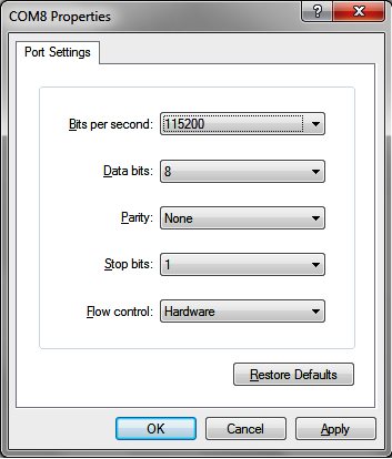
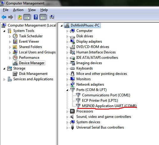
And this is my configure of HyperTerminal. ( I've already chosen right port of msp launch pad!)


  • Hi,

    You need to set your Flow Control to None in hyperterminal.  Also running 115200 baud with a source clock of 1 MHz has high error rates. You should have better luck setting your SMCLK to run at 8 MHz.

    HTH,

    Barry

  • Thank for your help!

    I  set your Flow Control to None in hyperterminal as you said and you use this code but it still doesn't work. Running in these clock and baud rate have low error rates according to user's guide.

    May you give me a code that can run ! 
    Thank you so much!
    //******************************************************************************
    // MSP430G2xx3 Demo - USCI_A0, 9600 UART Echo ISR, DCO SMCLK
    //
    // Description: Echo a received character, RX ISR used. Normal mode is LPM0.
    // USCI_A0 RX interrupt triggers TX Echo.
    // Baud rate divider with 1MHz = 1MHz/9600 = ~104.2
    // ACLK = n/a, MCLK = SMCLK = CALxxx_1MHZ = 1MHz
    //
    // MSP430G2xx3
    // -----------------
    // /|\| XIN|-
    // | | |
    // --|RST XOUT|-
    // | |
    // | P1.2/UCA0TXD|------------>
    // | | 9600 - 8N1
    // | P1.1/UCA0RXD|<------------
    //
    // D. Dang
    // Texas Instruments Inc.
    // February 2011
    // Built with CCS Version 4.2.0 and IAR Embedded Workbench Version: 5.10
    //******************************************************************************
    #include "msp430g2553.h"

    void main(void)
    {
    WDTCTL = WDTPW + WDTHOLD; // Stop WDT
    BCSCTL1 = CALBC1_1MHZ; // Set DCO
    DCOCTL = CALDCO_1MHZ;
    P1SEL = BIT1 + BIT2 ; // P1.1 = RXD, P1.2=TXD
    P1SEL2 = BIT1 + BIT2 ; // P1.1 = RXD, P1.2=TXD
    UCA0CTL1 |= UCSSEL_2; // SMCLK
    UCA0BR0 = 104; // 1MHz 9600
    UCA0BR1 = 0; // 1MHz 9600
    UCA0MCTL = UCBRS0; // Modulation UCBRSx = 1
    UCA0CTL1 &= ~UCSWRST; // **Initialize USCI state machine**
    IE2 |= UCA0RXIE; // Enable USCI_A0 RX interrupt
    UCA0TXBUF=0x41;
    __bis_SR_register(LPM0_bits + GIE); // Enter LPM0, interrupts enabled
    }

    // Echo back RXed character, confirm TX buffer is ready first
    #pragma vector=USCIAB0RX_VECTOR
    __interrupt void USCI0RX_ISR(void)
    {
    while (!(IFG2&UCA0TXIFG)); // USCI_A0 TX buffer ready?
    UCA0TXBUF = UCA0RXBUF; // TX -> RXed character
    }


  • Assuming that you use the LaunchPad, the baudrate is limited to 9600Bd. The USB/ser converter on the LaunchPad won't accept more.

    Also, check the jumpers on the board. The hardware UART pins on the G2553 are twisted against the original wiring on the older G2 LaunchPad chips with software UART.

  • oh! thank you very much! i will try !

  • I am having the same problem

    I have the MSP-EXP430G2 LaunchPad and and using a MSP430G2553 mc.

    I am trying to get the sample code to echo with my PC

    //******************************************************************************
    // MSP430G2xx3 Demo - USCI_A0, 9600 UART Echo ISR, DCO SMCLK
    //
    // Description: Echo a received character, RX ISR used. Normal mode is LPM0.
    // USCI_A0 RX interrupt triggers TX Echo.
    // Baud rate divider with 1MHz = 1MHz/9600 = ~104.2
    // ACLK = n/a, MCLK = SMCLK = CALxxx_1MHZ = 1MHz
    //
    // MSP430G2xx3
    // -----------------
    // /|\| XIN|-
    // | | |
    // --|RST XOUT|-
    // | |
    // | P1.2/UCA0TXD|------------>
    // | | 9600 - 8N1
    // | P1.1/UCA0RXD|<------------
    //
    // D. Dang
    // Texas Instruments Inc.
    // February 2011
    // Built with CCS Version 4.2.0 and IAR Embedded Workbench Version: 5.10
    //******************************************************************************
    #include "msp430g2553.h"

    void main(void)
    {
    WDTCTL = WDTPW + WDTHOLD; // Stop WDT
    BCSCTL1 = CALBC1_1MHZ; // Set DCO
    DCOCTL = CALDCO_1MHZ;
    P1SEL = BIT1 + BIT2 ; // P1.1 = RXD, P1.2=TXD
    P1SEL2 = BIT1 + BIT2 ; // P1.1 = RXD, P1.2=TXD
    UCA0CTL1 |= UCSSEL_2; // SMCLK
    UCA0BR0 = 104; // 1MHz 9600
    UCA0BR1 = 0; // 1MHz 9600
    UCA0MCTL = UCBRS0; // Modulation UCBRSx = 1
    UCA0CTL1 &= ~UCSWRST; // **Initialize USCI state machine**
    IE2 |= UCA0RXIE; // Enable USCI_A0 RX interrupt

    __bis_SR_register(LPM0_bits + GIE); // Enter LPM0, interrupts enabled
    }

    // Echo back RXed character, confirm TX buffer is ready first
    #pragma vector=USCIAB0RX_VECTOR
    __interrupt void USCI0RX_ISR(void)
    {
    while (!(IFG2&UCA0TXIFG)); // USCI_A0 TX buffer ready?
    UCA0TXBUF = UCA0RXBUF; // TX -> RXed character
    }


    I am using Teraterm COM5, 9600, 8n1, Flow Control none
    When I connect, I can't type anything into the terminal.  I thought that if I typed a character it 
    should echo back.  I have read tons of blog posts and articles but can't seem to get this figured out.
    
    
    **EDIT
    I can turn on local echo to see what I am typing in, but I still don't get an echo back from the MC.  I have tried both CR and CRLF for transmit modes.

**Attention** This is a public forum