This thread has been locked.

If you have a related question, please click the "Ask a related question" button in the top right corner. The newly created question will be automatically linked to this question.

SPI and USICKPH USI Clock Phase

First time I'm using SPI and as slave is a tiny QFN was not sure if it was working.

Spent 10 hours trying to get it to work.

FINALLy sucess with:
bis.b   #USIIE+USICKPH,&USICTL1         ; Counter interrupt, flag remains

Is that common that you need  USICKPH set?


            mov.b   &USISRL,&0200h               ; the result from last reading, move to ram for debuging.
            bis.b   #1<<7,&P2OUT                     ; nSEL high on slave
            nop           
            bic.b   #1<<7,&P2OUT                     ; nSEL low (active)                      
            mov.w   #0ffh,R4                              ; Delay for Slave
Delay   dec.w   R4                      
            jnz     Delay
            mov.w   #02500h,&USISR               ; send read command
            mov.b   #16+USI16B,&USICNT       ; init-load counter +16bit mode, clear flag 
            reti                                                    ; Exit ISR
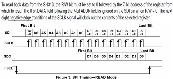
 

  • Tony Philipsson said:
    Is that common that you need  USICKPH set?

    Not all SPI devices use the same clock phase / polarity, and therefore the clock phase / polarity has to be selected according to the SPI device being used.

    The SPI Mode of the Users Guide for the MSP430 family has a Serial Clock Polarity and Phase diagram which shows the effect of the UCCKPL and UCCKPH control bits. Based upon the timing diagram for the Si4313 the correct settings are UCCKPH=1 and UCCKPL=0 which matches your working code.

  • The TI phase interpretation is different from the Motorola one.
    So setting USICKPH is the 'usual' configuration for many (but not all) SPI slaves out there.

**Attention** This is a public forum