This thread has been locked.

If you have a related question, please click the "Ask a related question" button in the top right corner. The newly created question will be automatically linked to this question.

Am I out of power?

Other Parts Discussed in Thread: MSP430F2013

I have a board I'm trying to program (the std MSP430F2013 PIR detector) with an MSP-FET430UIF (USB) in Windows XP on a laptop-base and failing unless I use external power - which is a pain. When I tried without external power I measured on pin 2 (pwr):

  • before start - 0V
  • on start of debug - 3V for 100ms then 0V for 100ms then repeating 1V spikes at about the same rate
  • finally, initializing hardware would fail and it would ask me to retry or cancel
  • on cancel the spikes stop (i think)

As far as I can tell the board correctly opens up pin 4 on the JTAG connector and it really shouldn't be drawing that much power (my lab supply says the power is about 10mA) but that's low-res.

Does anyone know if this is the symptom for an overpower condition or is it something else? The manual says 100mA but refers to the parallel port.

Thanks,

  Mark

  • I assume from your description, you have your own target hardware using the MSP430F2013, correct?

    If so, would you describe the connections to the MSP-FET430UIF?  Do you have Vcc of the MSP430 connected to pin 4 or pin 2 of the emulation pod?

    If you haven't already, please reference the MSP430 Hardware Tools User's Guide (SLAU278) in Section 2.  Figure 2-1 and Figure 2-2 illustrate the two possible connections and Section 2.2 describes that the USB MSP-FET430UIF can supply up to 100mA.


  • Hi,


    My target hardware is a Sparkfun PIR detector shown here: http://www.sparkfun.com/commerce/product_info.php?products_id=8645

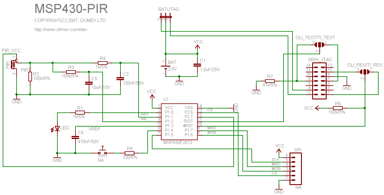
    I've checked on the schematic and using an ohmmeter and power is going to pin 2 and pin 4 is open (in the JTAG power mode which isn't working). In the BAT power mode (which works) pin 2 is disconnected and pin 4 is connected to Vcc. When I power it with the lab supply (acting like a battery) an inline ammeter says 20uA. Note that on the detector I've moved the jumpers to TI instead of OLIMEX. The Schematic is here: http://www.olimex.com/dev/images/MSP430/MSP430-PIR-sch.gif

    Oh, and when I use external power the UIF gui displays the sampled voltage.

    Thanks,

       Mark


  • I do not have your PIR board. But based on the schematics pointed by the URL you posted, it should work with the MSP-FET430UIF and power by USB as follows:

    The battery has to be removed.

    The solder bridges should be on TI-Test and TI-Reset side. Not on the OLI-Test or OLI-Reset side.

    The power select jumper should be on JTAG side, not on the Battery side.

    Does the PIR board matches this schemetic? On the actual board, is there any bypass capacitor larger than the 1uF as shown in the schematic? If so, that could cause problems if it interact with the JTAG power supply.

  • Without exhaustive testing I can't guarantee it matches the schematic but it sure seems to. The caps are all surface mount and have no markings so it's tough to tell what values they are but again it works fine with my lab supply.

    Does anyone know if  the symptoms match an overcurrent condition or is it something else (such as too much capacitance)?

    Mark


  • A big on board capacitor (or on board battery) can cause a momentary over-current. If you use a lab supply or an external battery, they do not care and the board will work. But the JTAG power supply has current limiting and feedback circuits. When it detects the momentary over-current, it will react to it and may produce the exact symptoms you have seen.

    You need to use an osciloscope and examine the current and voltage profile when you try to start your JTAG.

  • Hi,

    Thanks for the info. I'm getting a few more boards in to see if it's intrinsic to the circuit or maybe a production issue (or by my resolding the jumpers). As far as I can tell the circuit looks ok and a check with my scope at startup didn't see anything obvious. Is there a max capacitance rating on this thing that I'm missing somewhere? I also wanted to make sure it wasn't an issue with the programmer (which I don't think I've settled yet).

     Is there any way to just ask the UIF to set a DC supply voltage and see if it takes without going through the debug path?


**Attention** This is a public forum