This thread has been locked.

If you have a related question, please click the "Ask a related question" button in the top right corner. The newly created question will be automatically linked to this question.

UCA0RXBUF help!!!

Other Parts Discussed in Thread: SIMPLICITI, MSP430G2553

 is possible for me to force input into the UCA0RXBUF, (UART receive buffer channel 0).
If yes, how?
If no, How do I at least reset it?

  • Yes, you can use machine code to force any data into UCA0RXBUF. But it would not stick. Why do you want to do that?

    Same for P1IN etc.

  • hi,

    I am receiving serial data from a device at baud rate 9600 into the UART pin 3.5 at the EZ430 RF2500.

    Once I get this serial data input, an interrupt gets fired.

    After the control jumps into the ISR, I collect my 1 byte at-a-time data from the UCA0RXBUF into a variable and transmit that variable.

    The code for my end device is ass follows:


    #include "bsp.h"

    #include "mrfi.h"

    #include "nwk_types.h"

    #include "nwk_api.h"

    #include "bsp_leds.h"

    #include "bsp_buttons.h"

    #include "vlo_rand.h"

    #include "msp430x22x4.h"


    void linkTo(void);

    void MCU_Init(void);


    __no_init volatile int tempOffset @ 0x10F4; // Temperature offset set at production

    __no_init volatile char Flash_Addr[4] @ 0x10F0; // Flash address set randomly


    static uint8_t sPeerFrameSem;

    static uint8_t sJoinSem;

    linkID_t linkID1;


    void createRandomAddress(); 


    void main (void)

    {

      addr_t lAddr;

      WDTCTL = WDTPW + WDTHOLD;                 // Stop WDT

      { 

      // delay loop to ensure proper startup before SimpliciTI increases DCO

      // This is typically tailored to the power supply used, and in this case

      // is overkill for safety due to wide distribution.

        volatile int i;

        for(i = 0; i < 0xFFFF; i++){}

      }

      if( CALBC1_8MHZ == 0xFF )                 // Do not run if cal values are erased

      {

        volatile int i;

        P1DIR |= 0x03;

        BSP_TURN_ON_LED1();

       // BSP_TURN_OFF_LED2();

        while(1)

        {

          for(i = 0; i < 0x5FFF; i++){}

          //BSP_TOGGLE_LED2();

          BSP_TOGGLE_LED1();

        }

      }


      // SimpliciTI will change port pin settings as well

      P1DIR = 0xFF;

      P1OUT = 0x00;

      P2DIR = 0x27;

      P2OUT = 0x00;

      P3DIR = 0xC0;

      P3OUT = 0x00;

      P4DIR = 0xFF;

      P4OUT = 0x00;


      BSP_Init();


      if( Flash_Addr[0] == 0xFF && 

          Flash_Addr[1] == 0xFF && 

          Flash_Addr[2] == 0xFF && 

          Flash_Addr[3] == 0xFF )

      {

        createRandomAddress();                  // set Random device address at initial startup

      }

      lAddr.addr[0]=Flash_Addr[0];

      lAddr.addr[1]=Flash_Addr[1];

      lAddr.addr[2]=Flash_Addr[2];

      lAddr.addr[3]=Flash_Addr[3];

      SMPL_Ioctl(IOCTL_OBJ_ADDR, IOCTL_ACT_SET, &lAddr);

      BCSCTL1 = CALBC1_8MHZ;                    // Set DCO after random function

      DCOCTL = CALDCO_8MHZ;


      BCSCTL3 |= LFXT1S_2;                      // LFXT1 = VLO

      TACCTL0 = CCIE;                           // TACCR0 interrupt enabled

      TACCR0 = 12000;                           // ~ 1 sec

      TACTL = TASSEL_1 + MC_1;                  // ACLK, upmode


      // keep trying to join until successful. toggle LEDS to indicate that

      // joining has not occurred. LED3 is red but labeled LED 4 on the EXP

      // board silkscreen. LED1 is green.

      while (SMPL_NO_JOIN == SMPL_Init((uint8_t (*)(linkID_t))0))

      {

        BSP_TOGGLE_LED1();

        BSP_TOGGLE_LED2();;

        __bis_SR_register(LPM3_bits + GIE);     // LPM3 with interrupts enabled

      }

      // unconditional link to AP which is listening due to successful join.

      linkTo();

    }


    void createRandomAddress()

    {

      unsigned int rand, rand2;

      do

      {

        rand = TI_getRandomIntegerFromVLO();    // first byte can not be 0x00 of 0xFF

      }

      while( (rand & 0xFF00)==0xFF00 || (rand & 0xFF00)==0x0000 );

      rand2 = TI_getRandomIntegerFromVLO();


      BCSCTL1 = CALBC1_1MHZ;                    // Set DCO to 1MHz

      DCOCTL = CALDCO_1MHZ;

      FCTL2 = FWKEY + FSSEL0 + FN1;             // MCLK/3 for Flash Timing Generator

      FCTL3 = FWKEY + LOCKA;                    // Clear LOCK & LOCKA bits

      FCTL1 = FWKEY + WRT;                      // Set WRT bit for write operation


      Flash_Addr[0]=(rand>>8) & 0xFF;

      Flash_Addr[1]=rand & 0xFF;

      Flash_Addr[2]=(rand2>>8) & 0xFF; 

      Flash_Addr[3]=rand2 & 0xFF; 


      FCTL1 = FWKEY;                            // Clear WRT bit

      FCTL3 = FWKEY + LOCKA + LOCK;             // Set LOCK & LOCKA bit

    }


    void linkTo()

    {


      // keep trying to link...

     while (SMPL_SUCCESS != SMPL_Link(&linkID1))

      {

        __bis_SR_register(LPM3_bits + GIE);     // LPM3 with interrupts enabled

        BSP_TOGGLE_LED1();

        BSP_TOGGLE_LED2();

    }


      MCU_Init();


     while (1)

      {

        BSP_TURN_ON_LED2();

        __bis_SR_register(LPM3_bits+GIE);       // LPM3 with interrupts enabled

        SMPL_Ioctl( IOCTL_OBJ_RADIO, IOCTL_ACT_RADIO_AWAKE, "" );

          __bis_SR_register(CPUOFF + GIE);        // LPM0 with interrupts enabled

        results[0] = ADC10MEM;

        ADC10CTL0 &= ~ENC;

         __bis_SR_register(CPUOFF + GIE);        // LPM0 with interrupts enabled

        }

    }


    //..............SETTING UP THE UART PORT FOR ISR.....................

    void MCU_Init()

    {

      BCSCTL1 = CALBC1_8MHZ;                    // Set DCO

      DCOCTL = CALDCO_8MHZ;


      BCSCTL3 |= LFXT1S_2;                      // LFXT1 = VLO

      TACCTL0 = CCIE;                           // TACCR0 interrupt enabled

      TACCR0 = 12000;                           // ~1 second

      TACTL = TASSEL_1 + MC_1;                  // ACLK, upmode


      P3SEL |= 0x30;                            // P3.4,5 = USCI_A0 TXD/RXD

      UCA0CTL1 = UCSSEL_2;                      // SMCLK

      UCA0BR0 = 0x41;                           // 9600 from 8Mhz

      UCA0BR1 = 0x3;

      UCA0MCTL = UCBRS_2;                       

      UCA0CTL1 &= ~UCSWRST;  // **Initialize USCI state machine**


    IE2 |= UCA0RXIE; // Enable USCI_A0 RX interrupt

      __enable_interrupt(); 

    }


    //....................................................................


    static uint8_t sCB(linkID_t lid)

    {

      if (lid)

      {

        sPeerFrameSem++;

      }

      else

      {

        sJoinSem++;

      }

      return 0;

    }


    //..........TAKEN FROM SAMPLE CODE REFERRED FROM AP...............


    #pragma vector=ADC10_VECTOR

    __interrupt void ADC10_ISR(void)

    {

      __bic_SR_register_on_exit(CPUOFF);

    }


    //..........TAKEN FROM SAMPLE CODE REFERRED FROM AP..........


    #pragma vector=TIMERA0_VECTOR

    __interrupt void Timer_A (void)

    {

      __bic_SR_register_on_exit(LPM3_bits);        // Clear LPM3 bit from 0(SR)

    }


    //........................... ISR CODING..................................


    #pragma vector = USCIAB0RX_VECTOR

    __interrupt void USCIRX_ISR(void)

    {

      //linkID_t linkID1;

      uint8_t  msg[3];

    BSP_TURN_OFF_LED2();

    msg[0]=UCA0RXBUF;

      msg[1]=0x00;

      msg[2]=0x00;


     if (SMPL_SUCCESS == SMPL_Send(linkID1, msg, sizeof(msg)))

        {

          BSP_TURN_ON_LED1();

        }

     MCU_Init();

    }

    ................................................................................


    The reason why I want to clear the UCA0RXBUF is after I collect my 1st byte of data, I am still receiving serial data while I am transmitting, and I am falling out of sync at the receiver end.

    If I can clear the UCA0RXBUF, than I know for sure that no remains from the previous interrupt is left.

    Does that make sense?

    Hope I am explaining it clearly.


  • I do not think your method will work.

    The UART has a flag designed to resolve the concerns you have. This flag is called UCA0RXIFG, which is bit0 of IFG2 register. When you initially set up the UART, this flag should be cleared (=0). The UART is ready (and waiting) to receive incoming data. When the data arrives, it is stored in the UCA0RXBUF, the flag is automatically set (=1) and an interrupt is generated (if enabled). When you read UCA0RXBUF, the flag is automatically cleared (=0). When the next byte incoming data arrives, it will be stored in CA0RXBUF too. The flag will be set (=1) again and another interrupt will be generated again (if enabled). Thus if you use this mechanism properly, you will always get the all the UART incoming data once and only once.

  • Dear Friends

    I am testing the UART communications between MSP430G2553 and BNO055. I am sending 4 bytes as shown below and I must receive 3 bytes
    My question is how can I read these 3 bytes given that the UART buffer can accommodate one byte (as I understand).?
    And how can I read the receive buffer of the UART?
    And how can I turn on LED for a given received data?

    Thank you

    #include "msp430g2553.h" void main(void) { WDTCTL = WDTPW + WDTHOLD; // Stop the Watch dog //------------------- Configure the Clocks -------------------// if (CALBC1_12MHZ==0xFF) // If calibration constant erased { while(1); // do not load, trap CPU!! } DCOCTL = 0; // Select lowest DCOx and MODx settings BCSCTL1 = CALBC1_12MHZ; // Set range DCOCTL = CALDCO_12MHZ; // Set DCO step + modulation //---------------- Configuring the LED's ----------------------// P1DIR |= BIT0 + BIT6; // P1.0 and P1.6 output P1OUT &= ~BIT0 + BIT6; // P1.0 and P1.6 = 0 //--------- Setting the UART function for P1.1 & P1.2 --------// P1SEL |= BIT1 + BIT2; // P1.1 UCA0RXD input P1SEL2 |= BIT1 + BIT2; // P1.2 UCA0TXD output //------------ Configuring the UART(USCI_A0) ----------------// UCA0CTL1 |= UCSWRST; // **Put state machine in reset** UCA0CTL1 |= UCSSEL_3; // CLK = SMCLK // 115200 BAUD, CLK=12MHz UCA0BR0 = 6; //this is working UCA0BR1 = 0; //this is working //*ours: UCBRF = 8, UCBRS = 0, UCOS16 = 1 // UCBRF = 11, UCBRS = 0, UCOS16 = 1 // BITS| 7 6 5 4 | 3 2 1 | 0 | // UCAxMCTL = | UCBRFx | UCBRSx | UCOS16 | UCA0MCTL = 0x81; //this works fine { while( !(IFG2 & UCA0TXIFG) ); UCA0TXBUF = 0xAA; // Transmit a byte while( !(IFG2 & UCA0TXIFG) ); UCA0TXBUF = 0x01; // Transmit 2nd byte while( !(IFG2 & UCA0TXIFG) ); UCA0TXBUF = 0x00; // Transmit 3rd byte while( !(IFG2 & UCA0TXIFG) ); UCA0TXBUF = 0x01; // Transmit 4th byte } }

  • Neither you, nor your code knows when RX data is arriving. To be able to read RXBUF with meaningful data, first you need to either keep checking the RXIFG in a loop, or enable both RXIE and GIE and catch it in ISR. After that you can read RXBUF for one byte of data.
    To receive three bytes, you need to repeat the above sequence three times.
  • Thank you Old_cow_yellow

    Would please do me a favor and check this piece of code for me. I am checking if the 3rd byte I am getting back is A0, then is so, the LEDs should be turned on, but there not.

    Should I do the check inside the RX ISR? before it? or after it?

    Thank you

    #include "msp430g2553.h"
    unsigned int i;
    unsigned char data1;
    unsigned char data2;
    unsigned char data3;
    
    void main(void)
    {
      WDTCTL = WDTPW + WDTHOLD; // Stop the Watch dog
    
      //------------------- Configure the Clocks -------------------//
      if (CALBC1_12MHZ==0xFF)   // If calibration constant erased
         {
            while(1);          // do not load, trap CPU!!
         }
       DCOCTL  = 0;             // Select lowest DCOx and MODx settings
       BCSCTL1 = CALBC1_12MHZ;   // Set range
       DCOCTL  = CALDCO_12MHZ;   // Set DCO step + modulation
    
      //---------------- Configuring the LED's ----------------------//
    
       P1DIR  |=  BIT0 + BIT6;  // P1.0 and P1.6 output
       P1OUT  &= ~BIT0 + BIT6;  // P1.0 and P1.6 = 0
    
      //--------- Setting the UART function for P1.1 & P1.2 --------//
       P1SEL  |=  BIT1 + BIT2;  // P1.1 UCA0RXD input
       P1SEL2 |=  BIT1 + BIT2;  // P1.2 UCA0TXD output
    
      //------------ Configuring the UART(USCI_A0) ----------------//
       UCA0CTL1 |= UCSWRST;                      // **Put state machine in reset**
       UCA0CTL1 |= UCSSEL_3;                     // CLK = SMCLK
       // 115200 BAUD, CLK=12MHz
       		  UCA0BR0 = 6; //this is working
       		  UCA0BR1 = 0; //this is working
       		//*ours: UCBRF = 8, UCBRS = 0, UCOS16 = 1
       		  // UCBRF = 11, UCBRS = 0, UCOS16 = 1
       		  // BITS| 7 6 5 4 | 3 2 1  |   0    |
       		  // UCAxMCTL = | UCBRFx  | UCBRSx | UCOS16 |
       		  UCA0MCTL = 0x81; //this works fine
       		  UCA0CTL1 &= ~UCSWRST;             // Clear UCSWRST to enable USCI_A0-UART
    
      //---------------- Enabling the interrupts ------------------//
    
       		IE2 |= UCA0RXIE;                  // Enable the Receive  interrupt
       		_BIS_SR(GIE);                     // Enable the global interrupt
    
    {
    	while( !(IFG2 & UCA0TXIFG) );      // Check the buffer..wait it to be empty
    	UCA0TXBUF = 0xAA;                  // Transmit a byte
    
    	while( !(IFG2 & UCA0TXIFG) );      // Check the buffer..wait it to be empty
    	UCA0TXBUF = 0x01;                  // Transmit 2nd byte
    
    	while( !(IFG2 & UCA0TXIFG) );      // Check the buffer..wait it to be empty
    	UCA0TXBUF = 0x00;                  // Transmit 3rd byte
    
    	while( !(IFG2 & UCA0TXIFG) );      // Check the buffer..wait it to be empty
    	UCA0TXBUF = 0x01;                  // Transmit 4th byte
    }
    
    }
    #pragma vector=USCIAB0RX_VECTOR
    __interrupt void USCI0RX_ISR(void) {
    
    	if (IFG2 & UCA0RXIFG) 	{ 			// BNO055 response received
    		 data1 = UCA0RXBUF;			// Read 1st byte
    
    	}
    	if (IFG2 & UCB0RXIFG)
    	{				// BNO055 response received
    
    		data2 = UCB0RXBUF;			// Send Character to UART
    
    	}
    	if (IFG2 & UCB0RXIFG)
    	{				// BNO055 response received
    
    			data3 = UCB0RXBUF;			// Send Character to UART
    
    	}
    
    	if (data3 == 'A0')
    	              {
    	                     P1OUT^=(BIT0+BIT6);    // toggle the led's
    	                     for(i=0;i<20000;i++);    // delay between the toggle.
    	               }
    		else
    			P1OUT  &= ~BIT0 + BIT6;  // P1.0 and P1.6 = 0
    	
    }
    

  • if (data3 == 'A0')
    Warning[Pe1422]: multicharacter character literal (potential portability problem)

    C is not a string aware language.
    What you are doing is this: cmp.w #0x4130,&data3

    Never put a delay inside a ISR!!!!! plus a compiler in high optimization will warn that i is not used and/or just remove it.
    for(i=0;i<20000;i++);    // delay between the toggle.

    Your RX isr will not work like that, learn how to use pointers and length counter.

  • Something like this:

    #define   TXSTRING(pnt) (TXdata((pnt), sizeof(pnt)-1)) // cool macro to get string and string len
    uartstruct uart;                 // declare a struct from typedef uartstruct 
    
    void uart_init(void){
      IE2 &= ~(UCA0TXIE | UCA0RXIE | UCB0TXIE | UCB0RXIE); // Disable all USCIx0 TX & RX interrupts 
      UCA0CTL1 = UCSWRST;           // Set UCSWRST (hold USCI in Reset state)
      ... 
      IFG2 |= UCA0TXIFG;            // preset IFG flag always left on
    }
    
    void TXdata( char* pnt, unsigned int len){
      uart.bufpnt = pnt;                        
      uart.buflen = len;   
      uart.bufRXpnt = uart.RXbuffer;         // reset it to beginning of ram buffer
      IE2 |= UCA0TXIE + UCA0RXIE;            // enable USCI_A0 TX interrupt 
    }
    
    ...
    TXSTRING("\xAA\x01\x00\x01");           // hex escape inside a const string 
    
    //¦----------------------------- US0TX ISR  ---------------------------------------¦
    #pragma vector=USCIAB0TX_VECTOR 
    __interrupt void USCIAB0TX(void)                    // Shared A0/B0 TX IRQ vector
    {
      if (IFG2 & UCA0TXIFG){                            // our USCI_A0 transmit Interrupt?
                            
        if (uart.buflen){                               // if not zero
          UCA0TXBUF = *uart.bufpnt++;                  
          --uart.buflen;
        }
        else IE2 &= ~UCA0TXIE;                          // suspend IE if zero
      }
      else IFG2 &= ~UCB0TXIFG;                          // clear a false UCB0 trigger
    }
    
    //¦----------------------------- US0RX ISR  ---------------------------------------¦
    #pragma vector=USCIAB0RX_VECTOR 
    __interrupt void USCIAB0RX(void)                     // Shared A0/B0 RX IRQ vector
    { 
     if (IFG2 & UCA0RXIFG){                              // our USCI_A0 Recive Interrupt?
       *uart.bufRXpnt++ = UCA0RXBUF;                     // copy data byte 
      }
     else IFG2 &= ~UCB0RXIFG;    
    } 

  • Thank you, Tony

    I appreciate your reply. But I would like to ask you for more help (actually I am a student and really stuck as the semester is about to get ended and also because I am not good in C programming...will take c course during summer). 

    Would you please take a look at the code below after I rearranged it?

    The main function of this code is to send 4 bytes AA 01 00 01. And the received from the IMU (BNO055) should be BB 01 0A. So how can I check if the 3rd byte received is A0 and if so, turn on a LED? could please refer me to a piece of code does this?

    And regarding uartstruct uart; I am getting an error message that the uartstruct is undefined?

    Your help is highly appreciated

    Thank you


    Murtadha

    #include "msp430g2553.h"
    
       void setMSP430Pins() {
    	   //---------------- Configuring the LED's ----------------------//
    
    	   	      P1DIR  |=  BIT0 + BIT6;  // P1.0 and P1.6 output
    	   	      P1OUT  &= ~BIT0 + BIT6;  // P1.0 and P1.6 = 0
    
    	   	   //--------- Setting the UART function for P1.1 & P1.2 --------//
    
    	         P1SEL  |=  BIT1 + BIT2;  // P1.1 UCA0RXD input
    	         P1SEL2 |=  BIT1 + BIT2;  // P1.2 UCA0TXD output
    	         return;
       }
    
       void set_UCS() {
    	   //------------------- Configure the Clocks -------------------//
    
    	     DCOCTL  = 0;             // Select lowest DCOx and MODx settings
    	     BCSCTL1 = CALBC1_12MHZ;   // Set range
    	     DCOCTL  = CALDCO_12MHZ;   // Set DCO step + modulation
    
       }
    
    void uart_init(void){
      IE2 &= ~(UCA0TXIE | UCA0RXIE | UCB0TXIE | UCB0RXIE); // Disable all USCIx0 TX & RX interrupts
      UCA0CTL1 = UCSWRST;           // Set UCSWRST (hold USCI in Reset state)
      UCA0CTL1 |= UCSSEL_3;                     // CLK = SMCLK
    
       //------------ Configuring the UART(USCI_A0) ----------------//
        // 115200 BAUD, CLK=12MHz
        		  UCA0BR0 = 6; //this is working
        		  UCA0BR1 = 0; //this is working
        		//*ours: UCBRF = 8, UCBRS = 0, UCOS16 = 1
        		  // UCBRF = 11, UCBRS = 0, UCOS16 = 1
        		  // BITS| 7 6 5 4 | 3 2 1  |   0    |
        		  // UCAxMCTL = | UCBRFx  | UCBRSx | UCOS16 |
        		  UCA0MCTL = 0x81; //this works fine
    
    
        UCA0CTL1 &= ~UCSWRST;             // Clear UCSWRST to enable USCI_A0-UART
    
      IFG2 |= UCA0TXIFG;            // preset IFG flag always left on
    }
    
    #define   TXSTRING(pnt) (TXdata((pnt), sizeof(pnt)-1)) // cool macro to get string and string len
    uartstruct uart;                 // declare a struct from typedef uartstruct
    
    void TXdata( char* pnt, unsigned int len){
      uart.bufpnt = pnt;
      uart.buflen = len;
      uart.bufRXpnt = uart.RXbuffer;         // reset it to beginning of ram buffer
      IE2 |= UCA0TXIE + UCA0RXIE;            // enable USCI_A0 TX interrupt
    }
    
    
    //¦----------------------------- US0TX ISR  ---------------------------------------¦
    #pragma vector=USCIAB0TX_VECTOR
    __interrupt void USCIAB0TX(void)                    // Shared A0/B0 TX IRQ vector
    {
      if (IFG2 & UCA0TXIFG){                            // our USCI_A0 transmit Interrupt?
    
        if (uart.buflen){                               // if not zero
          UCA0TXBUF = *uart.bufpnt++;
          --uart.buflen;
        }
        else IE2 &= ~UCA0TXIE;                          // suspend IE if zero
      }
      else IFG2 &= ~UCB0TXIFG;                          // clear a false UCB0 trigger
    }
    
    //¦----------------------------- US0RX ISR  ---------------------------------------¦
    #pragma vector=USCIAB0RX_VECTOR
    __interrupt void USCIAB0RX(void)                     // Shared A0/B0 RX IRQ vector
    {
     if (IFG2 & UCA0RXIFG){                              // our USCI_A0 Recive Interrupt?
       *uart.bufRXpnt++ = UCA0RXBUF;                     // copy data byte
      }
     else IFG2 &= ~UCB0RXIFG;
    }
    
    void main(void) {
    	WDTCTL = WDTPW + WDTHOLD; // Stop the Watch dog
    
    	setMSP430Pins();
    	set_UCS();
    	uart_init();
    	TXSTRING("\xAA\x01\x00\x01");           // hex escape inside a const string
    
    }
    

  • Not tested, but something like this:

    typedef struct uartTag                    // UART
    {   char *bufpnt;                         // tx buffer pointer 
        unsigned int buflen;                  // the lenght of tx block 
        char *bufRXpnt;                       // uartRX buffer pointer
        char TXbuffer[10];                    // not always used if pointer is to const 
        char RXbuffer[20];                    // no protection against buffer overflow yet
    } uartstruct;
    while(1){ 
      TXSTRING("\xAA\x01\x00\x01");   
      __bis_SR_register(LPM0_bits + GIE);                  // Enter LPM0 Sleep with IRQ on
      if (uart.RXbuffer[2] == 0xA0)  P1OUT^=(BIT0+BIT6);   // toggle the led's
      __delay_cycles(12000);                               // small hard-loop delay
    } 

    Make these <<<< additions to RX ISR

    if (IFG2 & UCA0RXIFG){                            // our USCI_A0 Recive Interrupt?
      *uart.bufRXpnt++ = UCA0RXBUF;                   // copy data byte 
      if (uart.bufRXpnt == uart.RXbuffer+3)           // got three bytes in yet?  <<<<
         __bic_SR_register_on_exit(LPM0_bits);        // wakeup main              <<<<
     
  • Many thanks Tony,
    But just would like to make sure, I think uartTag should be uart only! since we are using it as this: uart.RXbuffer
    So there is no Tag I guess!
  • It's a typedef, that name is just a placeholder for compiler to use if something is wrong.

    Uartstruct is now the type, so that is why you don't see

    struct uartstruct uart

  • and regarding this section:
    I think uart.bufRXpnt = uart.RXbuffer;

    should be uart.bufTXpnt = uart.TXbuffer;

    void TXdata( char* pnt, unsigned int len){ uart.bufpnt = pnt; uart.buflen = len; uart.bufRXpnt = uart.RXbuffer; // reset it to beginning of ram buffer IE2 |= UCA0TXIE + UCA0RXIE; // enable USCI_A0 TX interrupt }

  • NO. It's there to reset the RX pointer at any new transmission as it expects a ping-pong-game

    bufpnt is set by the calling, a const string in a call is placed in flash and the location is set by compiler.

    Sure, could renamed bufpnt to bufTXpnt

    The macro saves you from having  to count how many chars or use a separate txdata function for strings.

    You can do TXdata((char *) 0x1000, 64); to send all of infod memory section for example

    Or custom fill txbuf with data and then TXdata(&uart.TXbuffer,10);

  • Tony,


    Many thanks for your support, it is working

    About the uart.RXbuffer[2], does this pointer start from 0? because for checking the 3rd byte we used 2?

  • Hi Tony


    I am now sending 5 bytes to set the slave device into a specific operation mode and I would like to read 6 registers and print there contents.

    So this line below I should replace to read the registers on the slave device and print the contents.

    if (uart.RXbuffer[2] == 0xA0) P1OUT^=(BIT0+BIT6); // Turn on the led's 

    Should I use printf? how to do that, is it by setting USCI_B0 as printf uses the UART?


    Thank you

    #include "msp430g2553.h"
    
    typedef struct uartTag                    // UART
    {   char *bufTXpnt;                        // UART TX buffer pointer
        unsigned int buflen;                  // the lenght of block
        char *bufRXpnt;                       // UART RX buffer pointer
        char TXbuffer[10];
        char RXbuffer[10];
    } uartstruct;
    
       void setMSP430Pins() {
    	   //---------------- Configuring the LED's ----------------------//
    
    	   	      P1DIR  |=  BIT0 + BIT6;  // P1.0 and P1.6 output
    	   	      P1OUT  &= ~BIT0 + BIT6;  // P1.0 and P1.6 = 0
    
    	   	   //--------- Setting the UART function for P1.1 & P1.2 --------//
    
    	         P1SEL  |=  BIT1 + BIT2;  // P1.1 UCA0RXD input
    	         P1SEL2 |=  BIT1 + BIT2;  // P1.2 UCA0TXD output
    	         return;
       }
    
       void set_UCS() {
    	   //------------------- Configure the Clocks -------------------//
    
    	     DCOCTL  = 0;             // Select lowest DCOx and MODx settings
    	     BCSCTL1 = CALBC1_12MHZ;   // Set range
    	     DCOCTL  = CALDCO_12MHZ;   // Set DCO step + modulation
    
       }
    
    void uart_init(void){
      IE2 &= ~(UCA0TXIE | UCA0RXIE | UCB0TXIE | UCB0RXIE); // Disable all USCIx0 TX & RX interrupts
      UCA0CTL1 = UCSWRST;           // Set UCSWRST (hold USCI in Reset state)
      UCA0CTL1 |= UCSSEL_3;                     // CLK = SMCLK
    
       //------------ Configuring the UART(USCI_A0) ----------------//
        // 115200 BAUD, CLK=12MHz
        		  UCA0BR0 = 6; //this is working
        		  UCA0BR1 = 0; //this is working
        		//*ours: UCBRF = 8, UCBRS = 0, UCOS16 = 1
        		  // UCBRF = 11, UCBRS = 0, UCOS16 = 1
        		  // BITS| 7 6 5 4 | 3 2 1  |   0    |
        		  // UCAxMCTL = | UCBRFx  | UCBRSx | UCOS16 |
        		  UCA0MCTL = 0x81; //this works fine
    
        UCA0CTL1 &= ~UCSWRST;             // Clear UCSWRST to enable USCI_A0-UART
    
      IFG2 |= UCA0TXIFG;            // preset IFG flag always left on
    }
    
    #define   TXSTRING(pnt) (TXdata((pnt), sizeof(pnt)-1)) // cool macro to get string and string len
    uartstruct uart;                 // declare a struct from typedef uartstruct
    
    void TXdata( char* pnt, unsigned int len){
      uart.bufTXpnt = pnt;
      uart.buflen = len;
      uart.bufRXpnt = uart.RXbuffer;         // reset it to beginning of ram buffer
      IE2 |= UCA0TXIE + UCA0RXIE;            // enable USCI_A0 TX interrupt
    }
    
    
    //¦----------------------------- US0TX ISR  ---------------------------------------¦
    #pragma vector=USCIAB0TX_VECTOR
    __interrupt void USCIAB0TX(void)                    // Shared A0/B0 TX IRQ vector
    {
      if (IFG2 & UCA0TXIFG){                            // our USCI_A0 transmit Interrupt?
    
        if (uart.buflen){                               // if not zero
          UCA0TXBUF = *uart.bufTXpnt++;
          --uart.buflen;
        }
        else IE2 &= ~UCA0TXIE;                          // suspend IE if zero
      }
      else IFG2 &= ~UCB0TXIFG;                          // clear a false UCB0 trigger
    }
    
    //¦----------------------------- US0RX ISR  ---------------------------------------¦
    #pragma vector=USCIAB0RX_VECTOR
    __interrupt void USCIAB0RX(void)                     // Shared A0/B0 RX IRQ vector
    {
     if (IFG2 & UCA0RXIFG){                              // our USCI_A0 Recive Interrupt?
       *uart.bufRXpnt++ = UCA0RXBUF;                     // copy data byte
       if (uart.bufRXpnt == uart.RXbuffer+3)           // got three bytes in yet?  <<<<
            __bic_SR_register_on_exit(LPM0_bits);        // wakeup main              <<<<
      }
     else IFG2 &= ~UCB0RXIFG;
    }
    
    void main(void) {
    	WDTCTL = WDTPW + WDTHOLD; // Stop the Watch dog
    
    	setMSP430Pins();
    	set_UCS();
    	uart_init();
    
    	while(1){
    	  TXSTRING("\xAA\x01\x3D\x01\x01");
    	  __bis_SR_register(LPM0_bits + GIE);     // else Enter LPM0 Sleep with IRQ on
    	  if (uart.RXbuffer[2] == 0xA0)  P1OUT^=(BIT0+BIT6);    // Turn on the led's
    
    	  __delay_cycles(5000);                               // small hard-loop delay
    	}
    
    	}
    

  • print the result will be hard with only one uart, and many msp430 only have one uart.
    Uart does not play nicely with multi-master/slave so it will be hard temporary redirect to terminal,
    unless uart slave device has enable so you can tell it to ignore this data not meant for it.

    But it would be easy to "resend" the data by just: TXdata(&uart.RXbuffer, 4);
    But you now need to enable terminal path way for TXpin , so you kind of need a multiplexer ic.


    So that is why SPI and I2C is nicer as they handle multi-slave just fine.

  • I am using MSP430G2553, so can't I use the USCI_A1 for printf?
  • Nope, G2553 only have these: A0 is uart/spi and B0 is spi/i2c
    so as you can see you have two spi.

    bit banging 9600 is also possible with any free gpio.
    But you could try to route so msp TXpin so it goes both to your device and Launchpad's backdoor uart.
    And by switching from 115K to 9600 baud back-and-forth may keep your device from accepting this data.
    if it does have enable/power down pin, you would just use that to stop if from seeing the data.

  • Yes I realized that, thank you Tony

    Now what I did is I placed a break point after setting the register of the slave device and sending the reading command. Since I am reading acceleration, then I need to read 6 registers of the slave device (2 registers for the x-axis (MSB & LSB), similar for the y-axis and z-axis). I used the piece below. But with this I can read only one register. How to read 6 register instead of 1 (i.e. using xAA\x01\x08\x01 and changing the 3rd byte each time) and then checking the 3rd byte that I receive in the RX buffer?

    Can I do that?

    Can I check them all?

    while(1){
    	  TXSTRING("\xAA\x00\x3D\x01\x01");       // Send this to the BNO055 to set up the ACC mode
    	  
    	  while( !(IFG2 & UCA0TXIFG) );      // Check the buffer..wait it to be empty
    
    	  TXSTRING("\xAA\x01\x08\x01");       // Send this to the BNO055 to read the x-axis ACC data
    	  __bis_SR_register(LPM0_bits + GIE);     // else Enter LPM0 
    
    	  __delay_cycles(12000);                               // small hard-loop delay
    	}
    
    	}

  • Just a unrolled loop is probaly easiest here, as it's only 6.
    BNO055 also have i2c, that I would say is more robust as master is in control of data coming in not like uart when RX always have to be on standby.

    TXSTRING("\xAA\x01\x08\x01");         // Send this to the BNO055 to read the x-axis ACC data
    __bis_SR_register(LPM0_bits + GIE);   // Then Enter LPM0 
    x = uart.RXbuffer[2];
    TXSTRING("\xAA\x01\x09\x01");         // Send this to the BNO055 to read the y-axis ACC data
    __bis_SR_register(LPM0_bits + GIE);   // Then Enter LPM0 
    y = uart.RXbuffer[2];
    TXSTRING("\xAA\x01\x10\x01");         // Send this to the BNO055 to read the z-axis ACC data
    __bis_SR_register(LPM0_bits + GIE);   // Then Enter LPM0 
    z = uart.RXbuffer[2];
    ...
  • Thank you Tonyy, I know that I2C is much better, but I have not mastered it., thus I started with UART

    OK, so I defined these

    char xLSB;

    char xMSB;

    char yLSB;

    char yMSB;

    char zLSB;

    char zMSB;

    and used the lines below as per your advice, but when checking xLSB, xMSB, etc. all there are 0x00!, what is wrong with what I am doing ?


    while(1){ TXSTRING("\xAA\x00\x3D\x01\x01"); // Send this to the BNO055 to set up the ACC mode while( !(IFG2 & UCA0TXIFG) ); // Check the buffer..wait it to be empty TXSTRING("\xAA\x01\x08\x01"); // Send this to the BNO055 to read the x-axis ACC data __bis_SR_register(LPM0_bits + GIE); // else Enter LPM0 xLSB = uart.RXbuffer[2]; while( !(IFG2 & UCA0TXIFG) ); // Check the buffer..wait it to be empty TXSTRING("\xAA\x01\x09\x01"); // Send this to the BNO055 to read the x-axis ACC data __bis_SR_register(LPM0_bits + GIE); // else Enter LPM0 xMSB = uart.RXbuffer[2]; while( !(IFG2 & UCA0TXIFG) ); // Check the buffer..wait it to be empty TXSTRING("\xAA\x01\x0A\x01"); // Send this to the BNO055 to read the y-axis ACC data __bis_SR_register(LPM0_bits + GIE); // else Enter LPM0 yLSB = uart.RXbuffer[2]; while( !(IFG2 & UCA0TXIFG) ); // Check the buffer..wait it to be empty TXSTRING("\xAA\x01\x0B\x01"); // Send this to the BNO055 to read the y-axis ACC data __bis_SR_register(LPM0_bits + GIE); // else Enter LPM0 yMSB = uart.RXbuffer[2]; while( !(IFG2 & UCA0TXIFG) ); // Check the buffer..wait it to be empty TXSTRING("\xAA\x01\x0C\x01"); // Send this to the BNO055 to read the z-axis ACC data __bis_SR_register(LPM0_bits + GIE); // else Enter LPM0 zLSB = uart.RXbuffer[2]; while( !(IFG2 & UCA0TXIFG) ); // Check the buffer..wait it to be empty TXSTRING("\xAA\x01\x0D\x01"); // Send this to the BNO055 to read the z-axis ACC data __bis_SR_register(LPM0_bits + GIE); // else Enter LPM0 zMSB = uart.RXbuffer[2]; __delay_cycles(5000); // small hard-loop delay }
  • while( !(IFG2 & UCA0TXIFG) );      // Check the buffer..wait it to be empty

    Can not use that, in this TX IRQ system IFG flag is never cleared as iE is enabled/disabled instead.
    As sending data, next chance to send more data will be after RX IRQ have recived 3 bytes and by that time TX is definitely ready for more bytes.

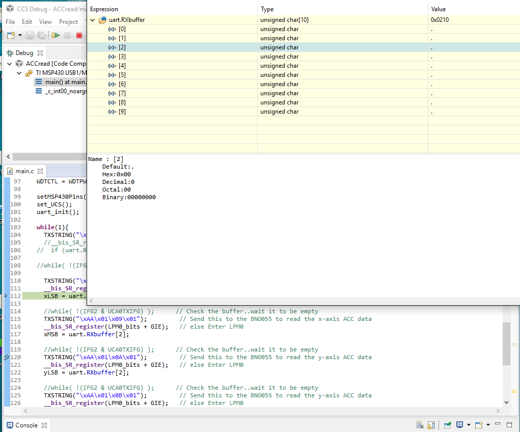
    what does the uart.RXbuffer look like?
    Do you see any data filled in?

  • uart.RXbuffer has these:
    uart.RXbuffer[0]: 0xBB.....which is correct, since the response of the BNO starts with BB
    uart.RXbuffer[1]: 0x01...also correct as this indicates the length
    uart.RXbuffer[2] to uart.RXbuffer[9]: 0x00...here is the problem
  • Ok, I commented all the
    while( !(IFG2 & UCA0TXIFG) );
    and use the debugger to check the RXbuffer (step by step, i.e. after sending the x-axis read command, etc) and there is no change, I am still getting BB 01 00
  • step by step don't work with uart running.
    put a break-point in front of example: yLSB = uart.RXbuffer[2];

    does it hit and what is the data in rxbuffer look like?

    Maybe have to change RX IRQ to a 4, as pointer is incremented before the compare, try it.

    if (uart.bufRXpnt == uart.RXbuffer+4)           // got three bytes in yet?  <<<<

  • Oh sorry, that is what I mean by step by step, I placed a BP and checked, I got BB 01 00
    But BB means the BNO has been red correctly and 01 means there is data of 1 byte coming
  • Edited:

    I changed it to 4, this is what I see.

    so I placed the BP in line 120, but it seems to be stuck in 112 (reading the x-axis) 

  • Hello Tony,


    I am still working on getting the correct data rather than 00. So do you think that I must check that the receive has been completed, read RXbuffer[2] before doing another  TX?

    Thank you

  • As receiving data can be any length, in your case it maybe always just 1 byte od data but you still

    Make the RX ISR read the second byte and is should not wake up main until it got all bytes.

    If main never wakes up you are waiting for one byte to much, subtract and 1 and try again.
    use a new RXbuflen as the cut off point to bic_SR

    if (uart.bufRXpnt == uart.RXbuffer+2 && uart.RXbuffer[0] == 0xBB)   
      uart.RXbuflen = uart.RXbuffer[1];
    
    if (!--uart.rxbuflen)           // got all bytes in yet? 
      __bic_SR_register_on_exit(LPM0_bits); // wakeup main
    

    Set uart.RXbuflen to 2 in TXdata subroutine

  • Ok Tony, SO i figured out how to read multiple registers in one shot. So I use this: \xAA\x01\x08\x06, which means that it will read 6 registers starting from 0x08 and this what I want.
    As such my code turned as below.
    I am checking if I gor 18 bytes, because I understand that the response will be like this
    0xBB 0x01 data(1-byte) this is repeated for 6 times. I am I correct?

    When doing this, I got 0xBB 0x06(indicating that 6 bytes of data are coming) and the rest are 0x00!
    Please note this 6 not 18. So what does that mean? is that mean that the data re only counted (BB and 01 before the data are excluded)

    And about these lines, How to make use of them in the new code? would you please do me a favor and insert them

    Many thanks:


    if (uart.bufRXpnt == uart.RXbuffer+2 && uart.RXbuffer[0] == 0xBB)   
      uart.RXbuflen = uart.RXbuffer[1];
    
    if (!--uart.rxbuflen)           // got all bytes in yet? 
      __bic_SR_register_on_exit(LPM0_bits); // wakeup main
    

    Set uart.RXbuflen to 2 in TXdata subroutine


    #include "msp430g2553.h"
    char xLSB;
    char xMSB;
    char yLSB;
    char yMSB;
    char zLSB;
    char zMSB;
    typedef struct uartTag                    // UART
    {   char *bufTXpnt;                        // UART TX buffer pointer
        unsigned int buflen;                  // the lenght of block
        char *bufRXpnt;                       // UART RX buffer pointer
        char TXbuffer[20];
        char RXbuffer[20];
    } uartstruct;
    
       void setMSP430Pins() {
    	   //---------------- Configuring the LED's ----------------------//
    
    	   	      P1DIR  |=  BIT0 + BIT6;  // P1.0 and P1.6 output
    	   	      P1OUT  &= ~BIT0 + BIT6;  // P1.0 and P1.6 = 0
    
    	   	   //--------- Setting the UART function for P1.1 & P1.2 --------//
    
    	         P1SEL  |=  BIT1 + BIT2;  // P1.1 UCA0RXD input
    	         P1SEL2 |=  BIT1 + BIT2;  // P1.2 UCA0TXD output
    	         return;
       }
    
       void set_UCS() {
    	   //------------------- Configure the Clocks -------------------//
    
    	     DCOCTL  = 0;             // Select lowest DCOx and MODx settings
    	     BCSCTL1 = CALBC1_12MHZ;   // Set range
    	     DCOCTL  = CALDCO_12MHZ;   // Set DCO step + modulation
    
       }
    
    void uart_init(void){
      IE2 &= ~(UCA0TXIE | UCA0RXIE | UCB0TXIE | UCB0RXIE); // Disable all USCIx0 TX & RX interrupts
      UCA0CTL1 = UCSWRST;           // Set UCSWRST (hold USCI in Reset state)
      UCA0CTL1 |= UCSSEL_3;                     // CLK = SMCLK
    
       //------------ Configuring the UART(USCI_A0) ----------------//
        // 115200 BAUD, CLK=12MHz
        		  UCA0BR0 = 6; //this is working
        		  UCA0BR1 = 0; //this is working
        		//*ours: UCBRF = 8, UCBRS = 0, UCOS16 = 1
        		  // UCBRF = 11, UCBRS = 0, UCOS16 = 1
        		  // BITS| 7 6 5 4 | 3 2 1  |   0    |
        		  // UCAxMCTL = | UCBRFx  | UCBRSx | UCOS16 |
        		  UCA0MCTL = 0x81; //this works fine
    
        UCA0CTL1 &= ~UCSWRST;             // Clear UCSWRST to enable USCI_A0-UART
    
      IFG2 |= UCA0TXIFG;            // preset IFG flag always left on
    }
    
    #define   TXSTRING(pnt) (TXdata((pnt), sizeof(pnt)-1)) // cool macro to get string and string len
    uartstruct uart;                 // declare a struct from typedef uartstruct
    
    void TXdata( char* pnt, unsigned int len){
      uart.bufTXpnt = pnt;
      uart.buflen = len;
      uart.bufRXpnt = uart.RXbuffer;         // reset it to beginning of ram buffer
      IE2 |= UCA0TXIE + UCA0RXIE;            // enable USCI_A0 TX interrupt
    }
    
    
    //¦----------------------------- US0TX ISR  ---------------------------------------¦
    #pragma vector=USCIAB0TX_VECTOR
    __interrupt void USCIAB0TX(void)                    // Shared A0/B0 TX IRQ vector
    {
      if (IFG2 & UCA0TXIFG){                            // our USCI_A0 transmit Interrupt?
    
        if (uart.buflen){                               // if not zero
          UCA0TXBUF = *uart.bufTXpnt++;
          --uart.buflen;
        }
        else IE2 &= ~UCA0TXIE;                          // suspend IE if zero
      }
      else IFG2 &= ~UCB0TXIFG;                          // clear a false UCB0 trigger
    }
    
    //¦----------------------------- US0RX ISR  ---------------------------------------¦
    #pragma vector=USCIAB0RX_VECTOR
    __interrupt void USCIAB0RX(void)                     // Shared A0/B0 RX IRQ vector
    {
     if (IFG2 & UCA0RXIFG){                              // our USCI_A0 Recive Interrupt?
       *uart.bufRXpnt++ = UCA0RXBUF;                     // copy data byte
       if (uart.bufRXpnt == uart.RXbuffer+18)           // got 18 bytes in yet?  <<<<
            __bic_SR_register_on_exit(LPM0_bits);        // wakeup main              <<<<
      }
     else IFG2 &= ~UCB0RXIFG;
    }
    
    void main(void) {
    	WDTCTL = WDTPW + WDTHOLD; // Stop the Watch dog
    
    	setMSP430Pins();
    	set_UCS();
    	uart_init();
    
    	while(1){
    	  TXSTRING("\xAA\x00\x3D\x01\x01");       // Send this to the BNO055 to set up the ACC mode (write)
    
    
    	  TXSTRING("\xAA\x01\x08\x06");         // Send this to the BNO055 to read 6 registers, 2 for each axis
    	  __bis_SR_register(LPM0_bits + GIE);   // else Enter LPM0
    	  xLSB = uart.RXbuffer[2];
    	  xMSB = uart.RXbuffer[5];
    	  yLSB = uart.RXbuffer[8];
    	  yMSB = uart.RXbuffer[11];
    	  zMSB = uart.RXbuffer[14];
    	  zMSB = uart.RXbuffer[17];
    	  __delay_cycles(12000);                               // small hard-loop delay
    	}
    
    }
    

  • Hi Tony,

    So I am modifying my post. Now my code looks like below. However I am still getting BB 06 and the rest are 0s

    Please correct me if I am doing anything wrong

    Thank you

    #include "msp430g2553.h"
    char xLSB;
    char xMSB;
    char yLSB;
    char yMSB;
    char zLSB;
    char zMSB;
    typedef struct uart                        // UART
    {   char *bufTXpnt;                        // UART TX buffer pointer
        char *bufRXpnt;                       // UART RX buffer pointer
        unsigned int TXbuflen;                  // the lenght of block
        unsigned int RXbuflen;
        char TXbuffer[10];
        char RXbuffer[10];
    } uartstruct;
    
       void setMSP430Pins() {
    	   //---------------- Configuring the LED's ----------------------//
    
    	   	      P1DIR  |=  BIT0 + BIT6;  // P1.0 and P1.6 output
    	   	      P1OUT  &= ~BIT0 + BIT6;  // P1.0 and P1.6 = 0
    
    	   	   //--------- Setting the UART function for P1.1 & P1.2 --------//
    
    	         P1SEL  |=  BIT1 + BIT2;  // P1.1 UCA0RXD input
    	         P1SEL2 |=  BIT1 + BIT2;  // P1.2 UCA0TXD output
    	         return;
       }
    
       void set_UCS() {
    	   //------------------- Configure the Clocks -------------------//
    
    	     DCOCTL  = 0;             // Select lowest DCOx and MODx settings
    	     BCSCTL1 = CALBC1_12MHZ;   // Set range
    	     DCOCTL  = CALDCO_12MHZ;   // Set DCO step + modulation
    
       }
    
    void uart_init(void){
      IE2 &= ~(UCA0TXIE | UCA0RXIE | UCB0TXIE | UCB0RXIE); // Disable all USCIx0 TX & RX interrupts
      UCA0CTL1 = UCSWRST;           // Set UCSWRST (hold USCI in Reset state)
      UCA0CTL1 |= UCSSEL_3;                     // CLK = SMCLK
    
       //------------ Configuring the UART(USCI_A0) ----------------//
        // 115200 BAUD, CLK=12MHz
        		  UCA0BR0 = 6; //this is working
        		  UCA0BR1 = 0; //this is working
        		//*ours: UCBRF = 8, UCBRS = 0, UCOS16 = 1
        		  // UCBRF = 11, UCBRS = 0, UCOS16 = 1
        		  // BITS| 7 6 5 4 | 3 2 1  |   0    |
        		  // UCAxMCTL = | UCBRFx  | UCBRSx | UCOS16 |
        		  UCA0MCTL = 0x81; //this works fine
    
        UCA0CTL1 &= ~UCSWRST;             // Clear UCSWRST to enable USCI_A0-UART
    
      IFG2 |= UCA0TXIFG;            // preset IFG flag always left on
    }
    
    #define   TXSTRING(pnt) (TXdata((pnt), sizeof(pnt)-1)) // cool macro to get string and string len
    uartstruct uart;                 // declare a struct from typedef uartstruct
    
    void TXdata( char* pnt, unsigned int len){
      uart.bufTXpnt = pnt;
      uart.TXbuflen = len;
      uart.bufRXpnt = uart.RXbuffer;         // reset it to beginning of ram buffer
      uart.RXbuflen=7;
      IE2 |= UCA0TXIE + UCA0RXIE;            // enable USCI_A0 TX interrupt
    }
    
    
    //¦----------------------------- US0TX ISR  ---------------------------------------¦
    #pragma vector=USCIAB0TX_VECTOR
    __interrupt void USCIAB0TX(void)                    // Shared A0/B0 TX IRQ vector
    {
      if (IFG2 & UCA0TXIFG){                            // our USCI_A0 transmit Interrupt?
    
        if (uart.TXbuflen){                               // if not zero
          UCA0TXBUF = *uart.bufTXpnt++;
          --uart.TXbuflen;
        }
        else IE2 &= ~UCA0TXIE;                          // suspend IE if zero
      }
      else IFG2 &= ~UCB0TXIFG;                          // clear a false UCB0 trigger
    }
    
    //¦----------------------------- US0RX ISR  ---------------------------------------¦
    #pragma vector=USCIAB0RX_VECTOR
    __interrupt void USCIAB0RX(void)                     // Shared A0/B0 RX IRQ vector
    {
     if (IFG2 & UCA0RXIFG){                              // our USCI_A0 Recive Interrupt?
       *uart.bufRXpnt++ = UCA0RXBUF;                     // copy data byte
       if (uart.bufRXpnt == uart.RXbuffer+8 && uart.RXbuffer[0]==0xBB)           // got 8 bytes in yet?  <<<<
    	   uart.RXbuflen=uart.RXbuffer[1];
    
    //   if(!--uart.RXbuflen)          //got all bytes in yet?
    //	   __bic_SR_register_on_exit(LPM0_bits);        // wakeup main              <<<<
      }
     else IFG2 &= ~UCB0RXIFG;
    }
    
    void main(void) {
    	WDTCTL = WDTPW + WDTHOLD; // Stop the Watch dog
    
    	setMSP430Pins();
    	set_UCS();
    	uart_init();
    
    	while(1){
    	  TXSTRING("\xAA\x00\x3D\x01\x01");       // Send this to the BNO055 to set up the ACC mode (write)
    
    
    	  TXSTRING("\xAA\x01\x08\x06");         // Send this to the BNO055 to read 6 registers, 2 for each axis
    	  if(!--uart.RXbuflen)          //got all bytes in yet?
    	//  	   __bic_SR_register_on_exit(LPM0_bits);        // wakeup main              <<<<
    
    	  xLSB = uart.RXbuffer[2];
    	  xMSB = uart.RXbuffer[3];
    	  yLSB = uart.RXbuffer[4];
    	  yMSB = uart.RXbuffer[5];
    	  zMSB = uart.RXbuffer[6];
    	  zMSB = uart.RXbuffer[7];
    	  __bis_SR_register(LPM0_bits + GIE);   // else Enter LPM0
    	//  __delay_cycles(12000);                               // small hard-loop delay
    	}
    
    }
    

  • Hi Tony,

    So the problem of getting 0s from the BNO055 is due to the fact that I am unable to set it to one of the sensing modes. When I set it to one of the sensing modes I get EE 03 which means, write failed. I would like to break up the write command, by sending one byte after another. May be this is the problem. I tried the following, but got EE 0A, which means ("> If a character arrives and the next character doesn’t arrive in
    the time frame of 100ms after that)!....is there a better way to do it?

    Thank you


    #include "msp430g2553.h"
    char xLSB;
    char xMSB;
    char yLSB;
    char yMSB;
    char zLSB;
    char zMSB;
    typedef struct uart                        // UART
    {   char *bufTXpnt;                        // UART TX buffer pointer
        unsigned int TXbuflen;                  // the lenght of TX block
        char *bufRXpnt;                       // UART RX buffer pointer
    
        unsigned int RXbuflen;                  // the lenght of RX block
        char TXbuffer[20];
        char RXbuffer[20];
    } uartstruct;
    
       void setMSP430Pins() {
    	   	   //--------- Setting the UART function for P1.1 & P1.2 --------//
    
    	         P1SEL  |=  BIT1 + BIT2;  // P1.1 UCA0RXD input
    	         P1SEL2 |=  BIT1 + BIT2;  // P1.2 UCA0TXD output
    	         return;
       }
    
       void set_UCS() {
    	   //------------------- Configure the Clocks -------------------//
    
    	  //   DCOCTL  = 0;             // Select lowest DCOx and MODx settings
    	     BCSCTL1 = CALBC1_12MHZ;   // Set range
    	     DCOCTL  = CALDCO_12MHZ;   // Set DCO step + modulation
    
       }
    
    void uart_init(void){
      IE2 &= ~(UCA0TXIE | UCA0RXIE | UCB0TXIE | UCB0RXIE); // Disable all USCIx0 TX & RX interrupts
    //  UCA0CTL1 = UCSWRST;           // Set UCSWRST (hold USCI in Reset state)
    //  UCA0CTL1 |= UCSSEL_3;                     // CLK = SMCLK
      UCA0CTL1|=UCSWRST;    //today added
      UCA0CTL1|= UCSSEL_2;  //today added
       //------------ Configuring the UART(USCI_A0) ----------------//
        // 115200 BAUD, CLK=12MHz
        		  UCA0BR0 = 6; //this is working
        		  UCA0BR1 = 0; //this is working
        		//*ours: UCBRF = 8, UCBRS = 0, UCOS16 = 1
        		  // UCBRF = 11, UCBRS = 0, UCOS16 = 1
        		  // BITS| 7 6 5 4 | 3 2 1  |   0    |
        		  // UCAxMCTL = | UCBRFx  | UCBRSx | UCOS16 |
        		  UCA0MCTL = 0x81; //this works fine
    
        UCA0CTL1 &= ~UCSWRST;             // Clear UCSWRST to enable USCI_A0-UART
    
      IFG2 |= UCA0TXIFG;            // preset IFG flag always left on
    
      IE2|=UCA0RXIE;  ///today added
    }
    
    #define   TXSTRING(pnt) (TXdata((pnt), sizeof(pnt)-1)) // cool macro to get string and string len
    uartstruct uart;                 // declare a struct from typedef uartstruct
    
    void TXdata( char* pnt, unsigned int len){
      uart.bufTXpnt = pnt;
      uart.TXbuflen = len;
      uart.bufRXpnt = uart.RXbuffer;         // reset it to beginning of ram buffer
    
      IE2 |= UCA0TXIE + UCA0RXIE;            // enable USCI_A0 TX & RX interrupt
    
    }
    
    //¦----------------------------- Delay Function  ---------------------------------------¦
    
    // This function will give us 1ms wait time, so for getting 10 ms,
    // then delay_ms(10) will give 10ms and delay_ms(100) will give 100ms
    void delay_ms(unsigned int ms)
    {
        unsigned int i;
        for (i = 0; i<= ms; i++)
           __delay_cycles(6000); // 6000 will give us 1ms
    }
    
    //void delay_ms(int del)     //generates delay in milliseconds
    //{
    //	del = (SysCtlClockGet()/3.0)*del/1000.0;
    //	SysCtlDelay(del);
    //}
    
    //¦----------------------------- US0TX ISR  ---------------------------------------¦
    #pragma vector=USCIAB0TX_VECTOR
    __interrupt void USCIAB0TX(void)                    // Shared A0/B0 TX IRQ vector
    {
      if (IFG2 & UCA0TXIFG){                            // our USCI_A0 transmit Interrupt?
    
        if (uart.TXbuflen){                               // if not zero
          UCA0TXBUF = *uart.bufTXpnt++;
          --uart.TXbuflen;
        }
        else IE2 &= ~UCA0TXIE;                          // suspend IE if zero
      }
      else IFG2 &= ~UCB0TXIFG;                          // clear a false UCB0 trigger
    }
    
    //¦----------------------------- US0RX ISR  ---------------------------------------¦
    #pragma vector=USCIAB0RX_VECTOR
    __interrupt void USCIAB0RX(void)                     // Shared A0/B0 RX IRQ vector
    {
     if (IFG2 & UCA0RXIFG){                              // our USCI_A0 Recive Interrupt?
    
       *uart.bufRXpnt++ = UCA0RXBUF;                     // copy data byte
       if (uart.bufRXpnt == uart.RXbuffer+8 && uart.RXbuffer[0]==0xBB)           // got 8 bytes in yet?  <<<<
    	   uart.RXbuflen=uart.RXbuffer[1];
    
      }
     else IFG2 &= ~UCB0RXIFG;
    }
    
    //¦----------------------------- Main  -------------------------------------------¦
    void main(void) {
    	WDTCTL = WDTPW + WDTHOLD; // Stop the Watch dog
    	//uart.RXbuflen=8;
    	setMSP430Pins();
    	set_UCS();
    	uart_init();
    
    	while(1){
    
    		TXSTRING("\xAA\x00\x3D\x01\x00");       // Send this to the BNO055 to set up the config mode (write)
    						//		while( !(IFG2 & UCA0TXIFG) );      // Check the buffer..wait it to be empty
    				delay_ms(10);
    
    		TXSTRING("\xAA\x00\x07\x01\x00");       // Page selection (page 0)
    			
    			delay_ms(10);	
    
    		TXSTRING("\xAA\x00\x3E\x01\x00");      // Normal Power mode
    
    		delay_ms(10);
    
    	// send the following to set the BNO to AMG mode (all sensors are on)
    			TXSTRING("\x01");
    
    			TXSTRING("\x3D");
    
    			TXSTRING("\x01");
    
    			TXSTRING("\x07");
    //	  xLSB = uart.RXbuffer[2];
    //	  xMSB = uart.RXbuffer[3];
    //	  yLSB = uart.RXbuffer[4];
    //	  yMSB = uart.RXbuffer[5];
    //	  zMSB = uart.RXbuffer[6];
    //	  zMSB = uart.RXbuffer[7];
    	// }
    	  __bis_SR_register(LPM0_bits + GIE);   // else Enter LPM0
    	 // __delay_cycles(12000);                               // small hard-loop delay
    	}
    
    }
    

**Attention** This is a public forum