This thread has been locked.

If you have a related question, please click the "Ask a related question" button in the top right corner. The newly created question will be automatically linked to this question.

Measuring Battery Voltage using ADC10 - Need Suggestion !

Other Parts Discussed in Thread: LP2950

Hi forum,

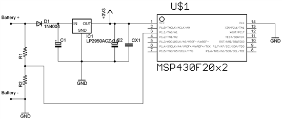
I am trying to build a simple Voltmeter to measure voltages between 0-15V,  I'm planning to power the circuit directly from the battery which i am measuring. My schematic is as above.

I know its not good practice to power the circuit from the source which is being measured, but i just want to display the measured voltage on 4 LEDs, i,e  10v_11V, 11v-12V, 12V-13V and 13V -14V range.  When the battery is connected the correct way i don't see any problem, but when the battery is connected reverse, will the Circuit survive. 

I have a diode in series to the regulator, but i am not sure about the internal clamp diodes which are available on the I/O pins, will the high voltage pass thru the Potential Divider, internal clamp diodes and reach Vcc thereby destroying the micro.

any suggestions would be welcomed and appreciated.

Regards,

Nischay

  • Put the protection diode before the divider

  • Then he would have to know the diode drop.

    Put a 15 volt Zener across the input and a low milliamp fuse in series with one of your inputs (to protect the Zener).

  • In that case, each time anyone connected the battery inverted... the fuse would blow.

    I still think a diode is a good choice, a carefully selected Schottky diode forward voltage wont vary more than 100mV under all load conditions

  • The internal clamping diode is go enough for up to 2 mA. Thus if (Vbat / R1) is less then 2 mA, nothing is going to get hurt.

  • Thanks for the replies,

    I cannot use diode before the P.D due to obvious reason, fuse with Zener is also not a good solution.

    as OCY suggested, there's no harm if my Vbat/R1 is less than 2mA, Values for R1 and R2 are 100K and 20K (1% tolerance).   when input is 15V, the ADC input pin will have 2.5V.

    @OCY, when the battery is connected in reverse, should it be Vbat/R1 or Vbat/R2 that i should be concerned ?


    Also, will the 3.3V Regulator survive in reverse connection, because the full Vbat voltage will be applied to its output pin (via uC Vcc)

    Regards,

    Nischay

  • I believe OCY is correct - you should be concerned with Vbat / R1 since the current would be flowing from Battery + (actually reversed to -15v), through R1, into the uC, out of the clamping diode(s) into ground. 

    The LP2950's are usually pretty tough, and it should be able to handle 150uA (15v / 100K) at -15v. However, since the voltage is divided through the divider down to -2.5v at the uC, then some sort of diode drops inside the uC before it reaches Vcc, I don't think there'd be any problem at all. Always got to try and make sure though...

    If it's still a problem, you could put like a 5v zener between ground and the output of the regulator. Normally the zener does nothing; but when <-0.7v is present on its output, the zener would clamp to ground.

    BTW, usually a mechanic lock-out from reverse polarity is best (ie AA batteries and connectors that can only go one way). Obviously this isn't always possible, so there are other combinations of diodes and resistors that can be used as well.

    - Chad

  • I agree that the polarized connector is the best solution.

    Second to that, I believe that a protection must work to stop the problem at its source. If you let the problem go inside, unknown factors multiply.

    I don't understand what are the obvious reasons for not putting the diode before the divider. Diode forward voltage is known within a tolerance more than enough for your application. And if that wasn't enough, you can use a self polarized MOSFET as blocking diode, so forward drop would be nil.

  • Thanks for Valuable insights,

    I think i'll try out the circuit and see what happens.

    @albert_83, the reason i don't want to use a diode in front of P.D is because of the temperature issues, since this circuit will be inside a car, and with windows closed the temp. inside a car can reach 65 deg. celsius within no time.

    Diode drop is directly related to temperature co-efficient.

    Regards

    Nischay

  • Forward drop for a schottky diode in a typ. application is 300mV@1mA, 400mA@10mA and 500mV@30mA. Voltage drop change from 20 degrees to 70 degrees will be            -100mV, for typ -2mv/°C. If that is not within your acceptable limits, you can use the self polarized MOSFET

    http://hackaday.com/2011/12/06/reverse-voltage-protection-with-a-p-fet/

    (You dont need the Zener for your app.)

    Good luck!

  • old_cow_yellow said:
    The internal clamping diode is go enough for up to 2 mA. Thus if (Vbat / R1) is less then 2 mA, nothing is going to get hurt.

    THis is true only if the MSP itself (or the total circuitry connected to VCC) draws mroe than these 2mA clamping current. Else VCC will start to rise, and most regulators cannot regulate down a too-high output voltage otehr than closing the from from input to output (which won't help in this case).

    But since the input requires a voltage, not a current, why not placing a series resisor of a few k between the voltage divider and the MSP input? It will effectively limit any excess current due to over/undervoltage.
    Depending on the voltage divider impedance, it will have some (small) impact to the ADC precision. However, this impact is much smaller than the influence of the ADCs own input impedance.

**Attention** This is a public forum