This thread has been locked.

If you have a related question, please click the "Ask a related question" button in the top right corner. The newly created question will be automatically linked to this question.

Powering problem: LM317 + MSP430G2553

Other Parts Discussed in Thread: LM317

Hi,

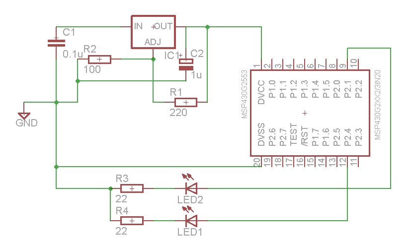
I have a little problem with my msp430.

I am sourcing it through a lm317 which transforms the 3.3v of a battery to 1.8 v. Then i am trying to light some leds. The problem is that it doesn´t work.

If a source the launchpad with the same program and battery it works.

Which should be the problem? Is it related to virtual ground?

I have checked all the connections and it's ok.

Thanks!!!

  • I do not know why you need to transform 3.3V to 1.8V. I do not know how you did it, And I do not know what happens.

    How can I help you?

  • I need 1.8 V because i will have a sensor connected to the msp430... (it works with 1.8 V).

    I did it with a lm317 ( https://www.national.com/ds/LM/LM317.pdf )

    The problem is that nothing happens. Whereas, doing the same to the launchpad it works ok.

    Now, i am connecting a dc transformer from main power to lm317 but i have a 50 hz wave in each led. Just in that pins of the msp430...

    It's really strange...

  • You should post your schematics. It looks liek you made something wrong ont he hardware side.

    However, remember the voltage drop over the por tpin 8depending on current) and the required forward voltage of the LEDs.

    a red LED usualyl ahs 1.7V forward voltage, that leaves only 0.1V headroom for the port pin driver adn will reuslt in only a very small current (maybe not small enough to light the LED)

    Leonardo Mart��nez said:
    Now, i am connecting a dc transformer from main power to lm317 but i have a 50 hz wave in each led. Just in that pins of the msp430...

    I fear, the LM317 is oscillating, emitting more than 1.8V periodically. Perhaps the input and/or output capacitors ont eh LM317 aren't suitable for the output of the DC transformer.

  • At 1.8V,MSP430G2xx cannot run above 6MHz. You also cannot erase or write to Flash memory. For that matter, JTAG Tools may not work with such a target.

  • It's actually running at 1Mhz (DCO). This is the schematic...

    Jens-Michael, the leds are checked, and should work fine.

    What do you suggest?

  • Measure the output of the LM317 with the MSP connected and disconnected. I think that it could be a problem on the power supply

  • It's the same (1.807 V) in both conditions.

    It's not about the power. I also have checked the output with the oscilloscope and it has almost none ripple. when I put the oscilloscope i also see 50 hz signal in each led...

  • You need to pull up /RST with ~47KOhm, and possibly a 10nF to ground. A 0.1uF across Dvcc and Dvss is also desirable to have.

  • Leonardo Mart��nez said:
    I am sourcing it through a lm317 which transforms the 3.3v of a battery to 1.8 v.

    3.3V input is below LM317 minimum input rating (3.7V ) 

    You need an suitable LDO regulator.

    Peter


  • Hi all,

    Thanks. I was forgetting the rst pin. How silly...

    The lm317 has no problems with that input. In the final design i will select another regulator. 

    Thanks.

  • Leonardo Mart��nez said:
    ...  I was forgetting the rst pin. How silly...

    No. That is not silly. Everybody forgets something from time to time.

    I think the silly part is to say "I have checked all the connections and it's ok", without telling people what "all the connections" are.  Next time when you have a problem, do not just say "I did everything correctly. Why does it not work?"

  • Leonardo Mart��nez said:
    the leds are checked, and should work fine.

    I just checked a yellow LED on my desk. It begins to glow on 1.7V. 1.8V for full brighness (10mA). On 10mA, the MSP port pins will have a voltage drop of ~0.6V. And also 220mV on your 22Ohm resistors. So to reach 10mA diode current, Vcc has to be 1.8+0.6+0.22= 2.62V. If I only have 1.8V Vcc, the diode will not have more than <1mA and barely visible.

    It's possible that you're operating right on the edge of glowing and non-glowing, where a minimum change on Vcc makes the LED go on and off. And your LM317 oscillates ust by a few mV around this point, driven by the also oscillating current consumption.

    When using a scope to check, use AC coupling and increase the sensitivity. This eliminates the base DC voltage and lets you see any ripple much, much better.

    Another things: teh 1µF capactor on teh LM output is for suppressing oscillations and shoudl be placed immediately next to the output (additonal 100nF ceramic won't hurt). However, you should have an additional >47µF capacitor near the MSP for stabilizing its VCC and swallowing any ripple caused by the MSp oepration and its alternating supply currents.

    In addition to this, the LM317 requires a minimum load of 3.5 to 10mA or it may become unstable. And the minimum input/output differential voltage (dropout voltage) is ~2V (increasing with current). Below that, the LM317 turns more or less into an unregulated series resistor.

  • Hi Jens.Michael,

    Thanks for your answer. I don't really care about the led performance. With my circuit they are draining 1,5 mA and i can see them. It's ok for me because it's just a prototype. I didn't know about that thing of the lm317. I will investigate more about how to properly transform 3.3 to 1.8 V.

    My problem was the reset pin that i didn´t remember. I used to work with pics which doesn't have that issue...

    Best Regards.

**Attention** This is a public forum