This thread has been locked.

If you have a related question, please click the "Ask a related question" button in the top right corner. The newly created question will be automatically linked to this question.

Controlling external LED with MSP and BC557B transistor

Other Parts Discussed in Thread: MSP430G2452

Hello everyone,

I'm new on MSP LaunchPad kit and I'm trying to setting a LED through a BC transistor. This is a test to, later, activate a DC motor through the smae mechanism.

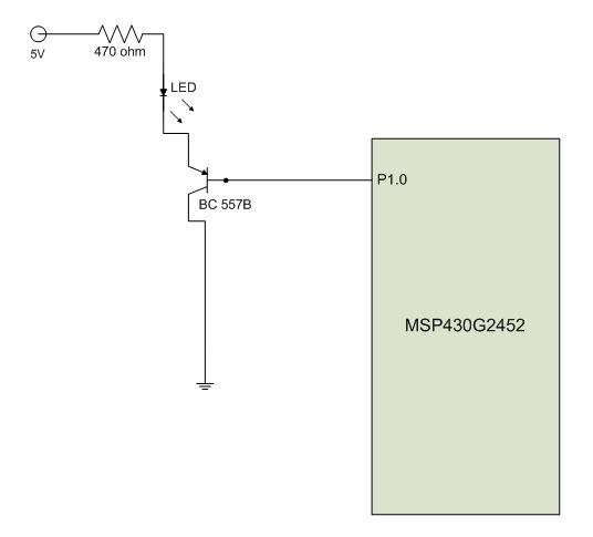
So, this is the schematic:

And the code:

#include "msp430g2452.h"

void main(void){

WDTCTL = WDTPW + WDTHOLD;                          //Turn off  Watchdog timer
P1DIR = 0xFF;                                                              // All pins are outputs

CCTL0 = CCIE;                                                            // Enable timer A comparator interrupt 
TACTL = TASSEL_2+MC_3+ID_3;                           // SMCLK = 1 MHz, SMCLK/8 = 125 KHz (8 us)
CCR0 = 62500;                                                            // Up/Down mode
                                                                                         // Each interrupt occurs at 2 * 62500 * 8us = 1s 
_BIS_SR(GIE);
while(1);

}
// Timer A0 interrupt service routine
#pragma vector=TIMER0_A0_VECTOR
__interrupt void Timer_A (void){
               P1OUT = P1OUT ^ 0x01;  // Alternates logic level in P1.0
}

So, the kit LED (P1.0) keeps blinking correctly, but the external LED doesn't. It keeps activate all the time. Even if i connect the base of the transistor to the GND pin on the MSP, it doesn't light off the LED. I'm powering the MSP through the USB cable on the PC and the code was made on the IAR IDE.

Can anyone tell me what I'm doing wrong?

Thanks. 

  • Consider yourself lucky if you did not damage the MSP430 chip.

    You should have used a NPN transistor instead. And you should have limited the base current with a resistor.

  • Hello Bruno,

    firstly you need to understand difference between NPN and PNP transistor. Your LED is active low. For closing transistor you need to give ~4V.

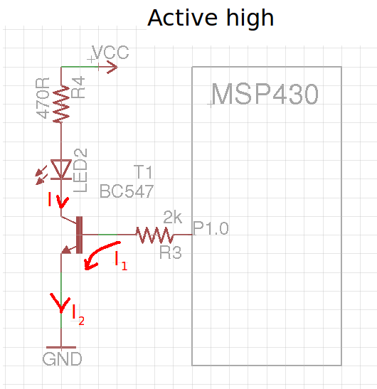
    Correct example circuits using NPN transistor (I2=I1+I):

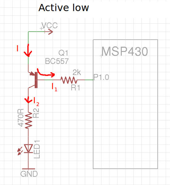
    Correct circuits using PNP transistor (I=I1+I2):

    Everything I wrote here you need to take with a pinch of salt since it describes transistors just a little and I recommend you to read about them (also datasheets with parameters) yourself.

    You can also think why you need to use resistor on base and why you are lucky you didn't destroy your MSP430 device. :)

    Solutions for you:

    1. Use transistor you have (BC557B) with example above and supply VCC from 3V source (e.g from Launchpad).

    2. Use NPN transistor (e.g. BC547).

    3. Connect:  VCC-> LED -> resistor -> P1.0 (active low) or GND<- LED <- resistor-< P1.0 (active high).


    Best regards,

    Mikolaj

  • Well, I've tried to limit the base current with a 1k resistor, but unsuccessfully. So I posted here the last setting done.

    =)

  • Mikolaj, thanks very much for the explanation.

    I just did the active low setting and works fine. Now I'll study more about the transistor and their operation.

    Well I was afraid that the output current from MSP was not enough to drive the transistor. What leads to my question: What is the output current and voltage from MSP when I set a pin to high level (e.g P1OUT |= BIT0)?

    About your suggestion (active low schematic), why I can't supply Vcc with 5V? This have something to do with the resistors values you put there? Or is there a problem when I supply MSP with the USB and the external LED with a 5V power supply?

    Thanks again.

  • Bruno, I would describe you here transistors in a few sentences, but it won't explain you whole working principles. There is a lot of pages where you can find much more info.

    Bruno Cazarim said:
    Well I was afraid that the output current from MSP was not enough to drive the transistor. What leads to my question: What is the output current and voltage from MSP when I set a pin to high level (e.g P1OUT |= BIT0)?

    When you read about transistors you will know you don' t need much current to drive it. In your mcu datasheet in "Output - Ports Px" section (page 20) you can find min/max and typical electrical parameters: VCC-0,3V for high state.

    Bruno Cazarim said:
    About your suggestion (active low schematic), why I can't supply Vcc with 5V? This have something to do with the resistors values you put there? Or is there a problem when I supply MSP with the USB and the external LED with a 5V power supply?


    In short, you can't use 5V with PNP transistor because the voltage level between base and emitter isn't sufficient to stop the flow.

    I advise you to use any simple simulator like: http://www.falstad.com/circuit/ . There you can check how your circuits will work (more or less) and for example what will happen when value of resistor on base will too high or low.

    Best regards,

    Mikolaj

  • Bruno Cazarim said:
    What is the output current and voltage from MSP when I set a pin to high level (e.g P1OUT |= BIT0)?

    They depend on each other. MSP is CMOS technology. If you doN't draw any current, output voltage reaches VCC (which is 3.6V max for the MSP). If you begin to draw current, output voltage drops. The datasheet has a diagram fo rthis. However, a typical value is that it drops to VCC-0.3V on 6mA current.

    However, transistors (bipolar ones are you're using), are unimpressed by voltage (unless it exceeds their maximum). The current from collector to emitter is controlled by the current between base and emitter. Typical transistors in the 100mA output current range have a beta of 100-400. That means for a collector current of n, you only need n/100 or even n/400 as base current. So 1mA is more than enough for a collector current of 100mA. (the bigger transistors for several A output have lower beta values of 10-50.)

    Since the transistor base has a 'base-emitter voltage' or roughly 0.5V, connecting th ebase directly to the MSP pin will make a base curent flow until the voltage breaks down to these 0.5V. Which can be a lot of current, destroying ht ebase. Hence the suggestion of a series resistor. With VCC=2.6V and a base current of 1mA, a series resistor of 3k is required. More for less base current.

    However, due to the CMOS transistor structure, you can directly put the LED on the MSP output. The shortcut current on the MSP pins is in the range of 15-25mA (and you don't exactly short them, as the LED has some voltage drop. YOu can see what current will flow through the LED for an LED voltage of x and an MSP supply voltage of x (and therefore yV-xV  drop on the port driver). See the already mentioned diagram in the datasheet.
    But since you want to drive a motor later...
    BNut with a motor, doN't forget that motor is an inductive load. It stores energy in the coil. And when you switch off the transistor and cut the current, this energy tries to break free, resulting in really high inverse voltages that may fry transistor and MSP. You'll need a so-called 'free running diode'.

    My suggestion is to use the ULN2003. It has 7 transistors and free-running diodes and has internal series resistors too. You can directly apply an MSP pin to its inputs and if the pin goes high, it will drive the associated output to GND for up to 500mA. Good for relay or motor or whatever.

  • Jens-Michael Gross,

    Thanks for the tips. I found the tables and diagrams for the output voltage from MSP and reading more about transistor could find my mistakes. For the motor, I knew that detail about inductive load, but thanks anyway.

**Attention** This is a public forum