This thread has been locked.

If you have a related question, please click the "Ask a related question" button in the top right corner. The newly created question will be automatically linked to this question.

Thermistor (PTC) interfacing with msp430 MCU.


Hello,

I have an appln. which require a PTC thermistor ( switching type, for motor winding temp. sensing appln) to be interfaced with MCU(msp4305xx) for temperature sensing. The thermistor will embedded on stator winding.The hw ckt will excite the PTC using constant current source.And mcu(adc) measure the voltage across it.

a)how to convert the adc value to realistic temperature value as the characteristic of the PTC thermistor is non-linear.What are the firmware method to be applied.

b) what should be the excitation current thru' Thermistor.should 0.1 mA  be ok?

the details as follows:

Total Resistance in Cold State = 1.5 K Ohm Per Sensor
Response Value 3.6 K Ohm.
Reset Value 1.6 K Ohm

rgds,ars

  • Ars said:
    how to convert the adc value to realistic temperature value as the characteristic of the PTC thermistor is non-linear.What are the firmware method to be applied.

    For an NTC, which also exhibits a nonlinear characteristic, I used some a lookup table built with Excel to translate voltage to temperature. Worked fine with 0.1°K resolution. We used it to stabilize the temperature of a high-power show laser where temeprature is critical for visible output to regulated current relation.
    For the switching type PTC this approach should work fine too.

    Ars said:
    what should be the excitation current thru' Thermistor.should 0.1 mA  be ok?

    The less the better. The current will cause self-heating. So no current would be best (but then you'll never know the resistance). The current does not need to be constant (you can calculate the distortion into the lookup table).
    We used a high-impedance setup folowed by an OpAmp to provide a low-impedance signal to the MSP (else the MSPs ADC input impedance becomes increasingly important with increasing sensor circuit impedance)

    However, if there is a tight coupling with the heat source, then the current-induced heating is less important. Some setups even route the operating current of the device through the thermistor,causign the operating current to instantly drop when the critical temperature is reached.

  • The motor temperature sensing is really simple.

    Since the critical temperature is reached at 3.6k, just use 3.6k resistor from the Vcc to drive the grounded thermistor.

    Use Vcc as the ADC reference voltage. Any value over 50% means the motor is exceeding safe temperature.

    You will need a 0.1uF capacitor on the ADC input to filter motor noise.

    Peter

  • Hello,

    Thanks for your reply.

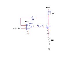
    I am using the current source(approx 0.1mA) to excite the thermistor(RL). RL = 100 Ohm .When I check (+) terminal of opamp with oscilloscope ,the waveform found oscillating (Saw tooth like waveform, mean value 2.5V DC but pk value 4.0 volt ). What causes the oscillation.How to resolve the issue.

    Regrds,

    ars

  • Ars said:
    What causes the oscillation


    As soon as + is above 2.5V, the output begins to raise until the transistor draws enough current so that there are 2.5V voltage drop on the 22k. I'm not sure what R1 is for, as it is in series with the probably several GOhms of the OpAmp input. However, this circuitry requires a very stable 2.5V reference. If the 2.5V on the negative pin are not very good filtered, any tiny change there will cause a significant change in the OpAmp output, which in turn will cause an even greater change in the current and therefore a massive change in the positive input.

    I guess the sawtooth you're seeing is the amplified ripple of your switching power supply. Give the 2.5V a series resistor and a capacitor to GND and the oscillation should cease.
    A larger value for the base resistor will also lessen the effect, as a larger voltage swing on teh output is required for a change of the transistor current.

  • Ars said:
    What causes the oscillation.How to resolve the issue.

    You have introduced a significant gain stage into the opamp feedback loop (- 22000/100)

    To stabilize this circuit place 1000pF cap between base and collector.

    However your circuit does not make much sense as the voltage on the thermistor will be 10mV.  

    A simple resistor from a reference voltage would work better.

    Peter

  • Peter Dvorak said:
    However your circuit does not make much sense as the voltage on the thermistor will be 10mV.  

    0.4mV if I calculated right: (2.5V/22k)*3.6k

    However, if you measure the OA output voltage and not the thermistor voltage, the switching point might be better. Especially if you raise the 30k to 100k or more. Raising the thermistor current would be another option. (lowering the 22k R2)

    Peter Dvorak said:
    A simple resistor from a reference voltage would work better.

    Sicne linear operation isn't necessary (only the switching point needs to be detected), this is maybe the way better solution. However, large currents through the thermistor may introduce significant self-heating.

    I guess, the OpAmp is better placed to amplify the thermistor voltage. Or the thermistor can be placed in the coupling loop of the OpAmp so the output has a large swing at the switching point.

    However, the constant ucrrent generator is a nice circuit I'll keep in mind :)

  • Jens-Michael Gross said:
    However, large currents through the thermistor may introduce significant self-heating.

    Another way is to lower self heating is to drive the source resistor only during the measurement cycle. 

    Peter

**Attention** This is a public forum