This thread has been locked.

If you have a related question, please click the "Ask a related question" button in the top right corner. The newly created question will be automatically linked to this question.

Interfacing SD_CARD with MSP430G2231

Other Parts Discussed in Thread: MSP430G2231, MSP430F1611, CSD, MSP430G2452

Hi,

at the moment I am trying to interface a SD Card with the MSP430G2231.

Therefore I´m using the MMC library functions provided by TI.

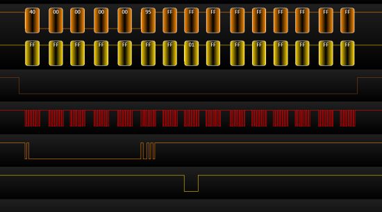
Now the problem is after sending the Go_Idle command to the SD Card it always responses

with a TIMEOUT_ERROR and I really can´t imagine why.

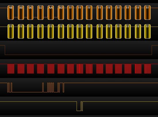
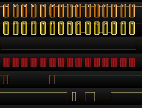
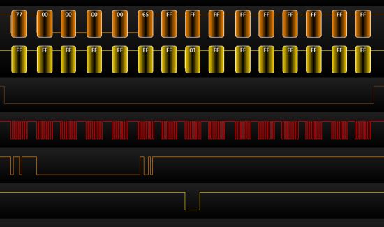
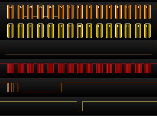
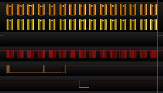
Maybe a bit more precise explanation :

First I raise Chip select and send some dummy bytes to the sd card for about 80 clock cycles.

Then I pull CS low and send the Go_Idle command to the sd. Afterwards I try to read the response of the

sd card and that´s where it answers with the timeout error.

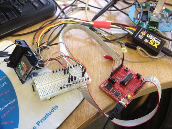
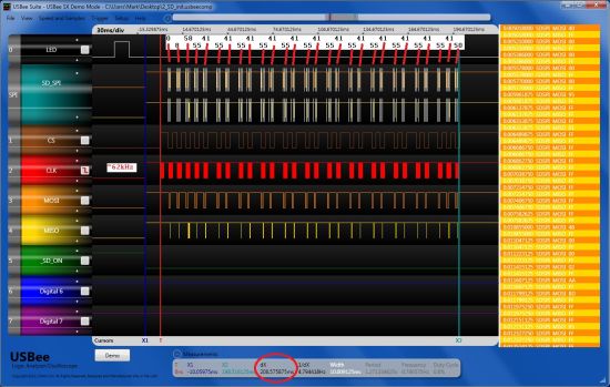
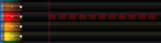
The voltage levels are perfectly correct ( I just measured it).

But I don´t know if the MSP430 clocks properly (can´t measure it because I have no scope).

So here´s my port initialization :

 WDTCTL = WDTPW + WDTHOLD;             // Stop watchdog timer

          P1OUT =  0x10;                        // P1.4 set, else reset
          P1DIR = 0x01;                         // P1.0 output, else input
          P1DIR |= SD_CS;                           // Set P1.4 to output direction Chip Select
          P1DIR |= SPI_SCLK;                        // Set P1.5 to output direction Master Clock
          P1DIR |= SPI_SDO;                         // Set P1.6 to output direction Data Output
         

          USICTL0 |= USIPE7 +  USIPE6 + USIPE5 + USIMST + USIOE; // Port, SPI master
          USICKCTL = USIDIV_4 + USISSEL_2 + USICKPL;      // /16 SMCLK
          USICTL0 &= ~USISWRST;                 // USI released for operation
          USISRL = 0x00;


          for (i = 0xFFF; i > 0; i--);          // Time for slave to ready
          USICNT = 1;                           // init-load counter

Hope somebody could help me.

Regards, Max

  • MaxE said:
              for (i = 0xFFF; i > 0; i--);          // Time for slave to ready
              USICNT = 1;                           // init-load counter

    This sets the USI to send one bit with SMCLK/16. However, the loop itself is faster than 16 MCLK (and therefore most likely SMCLK too) cycles.

    So you program the USI for another bit before it has sent the first bit, probably resettign the baudrate divider and nothing is ever sent. Jsu ta guess.

    You should do

    for(i=10;i>0;i--){ // send 80 bits
     USICNT = 8; // clears USIIFG, as long as USIIFGCC is clear
     while(USICTL1& USIIFG); // wait for 8 bits sent
    }

    Also, it might be necessary to set USICKPL. IIRC I had to do it on the USCI module (MSP430F1611) for SD card access for correct clock polarity (clock is inactive high and active low)

  • Hi Jens,

    I tried to get it run with the for loop you suggested but it didn´t work anyway. So what should the USICKPL look like ??

    It is set in this line :

    USICKCTL = USISSEL_2 + USICKPL +USIDIV_4;   

    should I set it up like this :

    USICKPL.IIRC

    And in my main function there´s this while loop :

              while(status!=0){

                  status = SD_Init();
                  timeout++;
                  if(timeout==150){

                      break;
                   }

              }
    the SD_Init() returns the Init_Error all the time.

    It looks like this :

    // Initialize SD card
    unsigned short SD_Init(void)
    {
      //raise CS and MOSI for 80 clock cycles
      //SendByte(0xff) 10 times with CS high
      //RAISE CS
      int i;

      //initialization sequence on PowerUp
      CS_HIGH();
      for(i=0;i<=9;i++)
        spiSendByte(DUMMY_CHAR);

      return (SD_GoIdle());
    }

    So the SD_GoIdle returns the Timeout_Error.

    // set SD in Idle mode
    unsigned short SD_GoIdle()
    {
      unsigned short response=0x01;
      CS_LOW();

      //Send Command 0 to put SD in SPI mode
      SDSendCmd(SD_GOIDLE,0,0x95);
      //Now wait for READY RESPONSE
      if(SDGetResponse()!=0x01)
        return SD_INIT_ERROR;

      while(response==0x01)
      {
        CS_HIGH();
        spiSendByte(DUMMY_CHAR);
        CS_LOW();
        SDSendCmd(SD_SEND_OP_COND,0x00,0xff);
        response=SDGetResponse();
      }
      CS_HIGH();
      spiSendByte(DUMMY_CHAR);
      return (SD_SUCCESS);
    }

    It always happens after sending the SD_GOIDLE command. The following SDGetResponse

    returns the Timeout_Error.

  • MaxE said:
    USICKCTL = USISSEL_2 + USICKPL +USIDIV_4;   

    Should do. IIRC, the clock mus tbe low-active, so CKPL needs to be set.

    MaxE said:
    the SD_Init() returns the Init_Error all the time.

    Sure? How do you know? You don't check for status in this loop.

    What library do you use? I only know the MMC libary (slaa281b), which more or less also applies to CD cards.

    However, a general quesiton: what size is your SD card? Newer cards, usually SDHC/SDXC cards, Especially those which claim to be 'high speed' do not implement the serial/SPI protocol anymore.
    Cards above 4GB (or sometimes even 2GB types), require a larger blocksize than the original 512 bytes and have a completely different configuration structure. Along with changing the internal organization, most manufacturers have also dropped the serial support.

    That SD_GOIDLE returns a timeout may indicate that your card doesn't support serial mode at all.

    Of course there's still a chance of a hardware problem. Does the card support the MSPs supply voltage? If they have separate supplies, what about the logic levels?

  • I'm not sure what the TI libraries do. But the following info might help.

    SPI mode in an SD card can only be engaged after a power cycle.

    Pin 1 (CS) must be held low as the power comes up or you will go into API mode.

    I had problems engaging a few SD cards and it turned out that although I thought I was power cycling SD card (SD Vcc On then Off) I was still driving some of the IO lines on the SD card so it didn't always see a true power cycle, and consequently stayed in API mode.

    I've got some SD-SPI code I could post but is written for a Freescale S08.....

    (cue boo's and hisses)  

  • When I´m debugging the code I can check the variable for the error code and it´s always the

    timeout error.

    Thw library I am using is the slaa281b.

    I´m using a Sandisk 1GB MicroSD card. So I think the 512 bytes blocksize is ok.

    It needs 2.7 V up to 3.6 V supply voltage and I´m driving it

    with the 3.6 V provided by the MSP430 Launch Pad.

    Is it possible that it doesn´t work with this card ??

    Does anybody know a card that surely works ??

  • @Jens : SPI mode should be fine on SDHC and SDXC. RE block size it was fixed at 512 bytes in SDHC and SDXC. SDSC can also use 512 bytes, but optionally less if the mfg supported it.

    @MaxE: In my experience if anything is going to work a SANDISK will.

  • Mark Green said:
    Pin 1 (CS) must be held low as the power comes up or you will go into API mode.

    Sure about this? I just checked my code and no, when inserting the card, CS is high. And so it is if the card is inserted and power is applied to both, MSP and card (well, of course the signal is in high-impedance state at first, before the MSP port pin switches to high output).
    It still works perfectly, whether I insert the card while the MSP is powered and CS is high, or whether I switch the power on with the card inserted.

    My code works with MMC, SD (up to 2GB) and microSD cards (which behave a bit different than normal SD cards in that they don't accept CMD1 whereas normal MMC cards do accept CMD1 and ACMD41 and MMC cards of course won't accept ACMD41). So I don't think it is necessary to have CS low on power-up. Or I was just lucky getting only cards that didn't require it :)

    I just took a look into the SD card specs V1.01 and it reads:

    "The SD Memory Card wakes up in the SD mode. It will enter SPI mode if the CS signal is asserted (negative) during the reception of the reset command (CMD0) and the card is in idle_state"

    So it always enters SD mode (the parallel mode, which I think is what you call API mode) on power-up and the state of CS determines whether it goes into SPI mode or not.
    Independently of mode, commands are always transmitted serially, only data transfers are done parallel.
    Of course there might have been an update to the standard since I wrote my code a few years ago. (Well, there definitely was, for SDHC and SDXC), but I don't have the newer specs.

  • Mark Green said:
    SPI mode should be fine on SDHC and SDXC.

    I got a couple of SDHC cards that refused to run in SPI mode. But maybe this was because these cards will indeed require CS low on power-up (which tehy never got from my hardware).
    About the 512 bytes, well, it is impossible to express a card size >1GB with the original, MMC-card compatible CSD structure and 512 bytes block size.

    C_SIZE_MULT is 512 max, and C_SIZE is 4095 max, which gives a factor of 2097152*READ_BL_LEN. 1GB for 512 byte read block length. And since READ_BL_LEN is 2048 max, 4GB is the maximum size that can be expressed at all - with 2k block size then. Also, the data read command only has a 32 bit address (which isn't a block address but a byte address).

    For anything above, the CSD needed to be changed, which is then no longer compatible to SD cards with the older CSD or MMC cards. And I noticed that manufacturers seemed to drop SPI mode at all for those cards, as those cards didn't respond at all. So I turned them down. 1GB was more than enough for all projects so far.
    Maybe it's time to think about a code extension. :) Do you have a link for the newest specs?

  • Jens-Michael Gross said:
    Sure about this?

    Obviously not... Just pulled up some of my old screen shots from the setup on this and your right, my CS is not held low from the get go. It goes low just before the first CMD. But the screen shot did remind me of what my original problem was. 

    The problem I had was the following:

    - I would plug an SD card in and sometimes it would enter SPI mode, sometimes it wouldn't.

    - Power cycle of the SD card rail would not cure the problem. (i.e. if it didn;t respond the first time, it wouldn't respond after a rail cycle.)

    - But if the whole board was powered down then brought back up again it might work.

    I think the problem was that if an SD card was plugged in while the socket was live then this would sometimes be interpreted as a false command by the SD card. Stopping entry into SPI mode (since this must be the first command after a power cycle). Subesequent rail cycles were not working because although the rail was dropped, the SPI lines were kept up (so keeping the SD card alive) .

    The cure was to drop all interface lines to 0V. Then the rail to 0V. Then bring the rail back up followed by the interface lines.

    It doesn't matter if CS is brought up at this point so long as it goes back down before the first command as Jens rightly points out.

    So to finish the sequence I found to be quite reliable was:

    - All lines low, and SD rail low

    - SD rail up

    - SPI on, (CS can go up as well)

    -  Send lots of 0xFF over the SPI (~80+clocks should do)

    - CS low

    - CMD0 (0x40) and off you go.....


    Apologies for the CS low on powerup curveball.... 

  • I should point out by off you go I mean carry on with the config, not your ready for data transfer.

    See p114 in the spec for more on the config command sequence:

    https://www.sdcard.org/downloads/pls/

  • Jens-Michael Gross said:
    I got a couple of SDHC cards that refused to run in SPI mode. But maybe this was because these cards will indeed require CS low on power-up

    Nope not due to the CS that my false info.


    Jens-Michael Gross said:
    C_SIZE_MULT is 512 max, and C_SIZE is 4095 max, which
    .... 

    Page 125 of the spec explains this. But briefly:

    Block size is fixed at 512 bytes for SDHC and SDXC. i.e. CMD16 (SET_BLOCKLEN) no longer does anything.

    With blocks fixed at 512 bytes in HC/XC this gave them a bit of flexibility on the read commands (CMD17, CMD18). For these cards  the 32bit address field is no longer a byte address it is a block address. 512 bytes * 2^32 = 2048 GB (if my maths is correct...)

  • So to point this out very clearly.

    How should I do the init.

    This is my code :

              unsigned short status=1;
              unsigned int timeout=0;

              // SPI_Setup

              volatile unsigned int i;

              WDTCTL = WDTPW + WDTHOLD;             // Stop watchdog timer

              P1OUT =  0x10;                        // P1.4 set, else reset
              P1DIR = 0x01;                         // P1.0 output, else input
              P1DIR |= SD_CS;                           // Set P1.4 to output direction Chip Select
              P1DIR |= SPI_SCLK;                        // Set P1.5 to output direction Master Clock
              P1DIR |= SPI_SDO;                         // Set P1.6 to output direction Data Output

              USICTL0 |= USIPE7 +  USIPE6 + USIPE5 + USIMST + USIOE + USISWRST; // Port, SPI master
              USICKCTL = USISSEL_2 + USICKPL +USIDIV_4;      // /16 SMCLK
              USICTL0 &= ~USISWRST;                 // USI released for operation

              USISRL = 0x00;
              USICNT = 1;

              for(i=10;i>0;i--){ // send 80 bits
               USICNT = 8; // clears USIIFG, as long as USIIFGCC is clear
               while(USICTL1& USIIFG); // wait for 8 bits sent
              }

              while(status!=0){

                  status = SD_Init();
                  timeout++;
                  if(timeout==150){

                      break;
                   }

              }

    You can read the SD_Init code  a few posts above.

    Could it work like this ??

  • Hi Max,

    You are using CMD1 to initialise an SD card. Not all SD cards support the MMC method of initialisation, and it is not recommended even if they do. 

    If its an SD card you should be using CMD0 >> CMD8 >> ACMD41.

    I'll post a step through of the ACMD process on Monday.... If you can't wait download the physical spec (link above) then read section 7 SPI.

    @Jean: If you were doing the same, then this is why your SDHC cards were not responding. SPI mode for these cards will not proceed without going down the correct route.

    Mark.

  • Mark Green said:
    If you were doing the same, then this is why your SDHC cards were not responding. SPI mode for these cards will not proceed without going down the correct route.

    No, my init sequence is

    - wait for CARD_DETECT signal
    - init SPI
    - 80 clock pulses
    - GO_IDLE_STATE
    - no response? go back to init SPI
    - MMC_APP_CMD
    - response == 4: try GO_IDLE_STATE/MMC_SEND_OP_COND istead (MMC)
    - response == 1: retry MMC_APP_CMD
    - response == 2: MMC_READ_CSD
    - check for valid (supported) card geometry.
    - done

    Well, the last step needs ot be expanded, as well as the address field in the data read/write functions.

    Mark Green said:
    Not all SD cards support the MMC method of initialisation, and it is not recommended even if they do. 

    MicroSD cards do not support MMC_SEND_OP_COND anymore. Mini and normal SD cards do, at least the pre-SDHC ones.
    This way you can (in theory, as it would require double-init) tell micro-SD from the others.

  • The initialization seems to work now at least the card responds with a 0x00 which

    means success.

    I just modified the SDGetResponse() function a bit

    here`s the code :

    // SD Get Response
    unsigned short SDGetResponse(void)
    {
      //Response comes 1-8bytes after command
      //the first bit will be a 0
      //followed by an error code
      //data will be 0xff until response
      int i=0;

      unsigned short response;

      while(i<=64)
      {
        //response=spiSendByte(DUMMY_CHAR);

              response=SPIRXBUF;
        if(response==0x00)break;
        if(response==0x01)break;
        i++;
      }
      return response;
    }

    Sending the DUMMY_CHAR seems to cause trouble. Though when I write

    response=SPIRXBUF;

    it works (not every time but at least 90 % of the tries).

    But now there´s another problem which I will mention in another thread.

    It´s about malloc. The debugger says there´s no source for malloc.

  • MaxE said:
    //response=spiSendByte(DUMMY_CHAR);

              response=SPIRXBUF;

    I might be missing something here... 

    by commenting out the spiSendByte() routine you are no longer providing a clock signal for the SD card to send you the response.

    Then you read the empty spi rx buffer.

    Which I guess defaults to 0 when empty - Jens might have more of an idea on this one?

  • On the USI module, the SPIRXBUF is the same as SPITXBUF.

    Dependign on the number of bits to transfer, the bits are shifted out of and back into thsi buffer. So if you don't do a transfer, you should simply read what was previously written to it (but not sent because no transfer was started by stuffing the count register.
    And yes, if nothing was written or transfererred so far, the content migh tbe zweo. But I think the code has already generated (dummy) clock pulses and sent a command, so this will likely be the 'dummy' return value sent by the card while the command was received (and not the answer to the command).
    However, the response should come at latest 8 bytes, not 64 (dummy) bytes after the command.

    One more thing: What is the clock running at? After power-up, the maximum SPI baudrate is limited to 400kHz IIRC. Only after initialization, it may go up to 12.5/25MHz (depending on card type 1.x or 2.x, found in the CSD)

  • Jens-Michael Gross said:

    One more thing: What is the clock running at? After power-up, the maximum SPI baudrate is limited to 400kHz IIRC. Only after initialization, it may go up to 12.5/25MHz (depending on card type 1.x or 2.x, found in the CSD)

    The DCO runs MCLK at 1 MHz according to the datasheet.

    I choose SMCLK but I do not know if there`s a divider.

    Then I choose a divider of four. So it should run at 250 kHz (can´t verify this one because I have no scope).

    Jens-Michael Gross said:

    Dependign on the number of bits to transfer, the bits are shifted out of and back into thsi buffer. So if you don't do a transfer, you should simply read what was previously written to it (but not sent because no transfer was started by stuffing the count register.
    And yes, if nothing was written or transfererred so far, the content migh tbe zweo. But I think the code has already generated (dummy) clock pulses and sent a command, so this will likely be the 'dummy' return value sent by the card while the command was received (and not the answer to the command).
    However, the response should come at latest 8 bytes, not 64 (dummy) bytes after the command.

    So this means when I uncomment the spiSendByte function I won´t get the correct response

    respectively the response I get is not the response to the command ??!!

  • MaxE said:
    respectively the response I get is not the response to the command ??!!

    Right.

    The last bit of the 'response' is received at the same clock pulse the last bit of the 'command' is sent. So it obviously cannot be the response to the command. It is the response to the previously sent byte (or a dummy if there was no response).

    spiSendByte always returns the byte received while the (command) byte was sent. Not the answer to the sent byte.

    To get the real response to the command, you'll have to send another (dummy) byte. This is why the loop sends up to 8 bytes for the response until giving up. (and because the SD card might be busy on the command for a few byte times).

  • Oh man I see no possibility of getting this run.

    Maybe I should try another card ?!!

  • Don't give up Max... I'll see if I can find my lauchpad dev kit.

  • Let´s sum up what we´ve got.

    The SD card doesn´t enter the IDLE Mode after sending the Go_Idle command, but

    responds with an timeout error.

    I checked the code step by step according to your posts and checked the voltage levels at the card.

    What I can´t check is the clock frequency but it should be 250 kHz which would be fine.

    So I can´t imagine any reason why this fails !!

    Maybe there´s a problem with the clock....

    Might it be that there´s this function needed to be set manually so that the pin clocks ??

    There`s this register to set the secondary pin functions, but don´t know how to use it and the datasheet

    doesn´t tell it very clearly either.

    It´s the P1SEL register. Do I firstly have to activate the SPI functions ??

    Or another suggest : is the clock frequency to slow ?? Maybe the over all divider is more than four ...

    I read in the SD specs that the clock should be run at 100 to 400 kHz at initialization.

  • I think you might be on the right lines with the P1SEL register.

    Look at table 71 on p41 of the MSP430G2231 datasheet.

    For SDO on P1.6 it says it doent care about the value in P1DIR and P1SEL but you need USIP set (which you have done).

    I found out the hard way that it is surprisingly common for Ti to make mistakes in this section.

    If you look at the datasheet for a very similar part: MSP430G2452, it states that P1SEL does need to be set for these pins to work as SPI. So I would be inclined to try the following:

    P1SEL = 0x80 + 0x40 + 0x20;  // pins to USI/SPI control

    If they really are dont care then it shold matter if you set them.

    I've just about finished coding up on my lauchpad but I left my SD connector at work.

    I'll get it running tomorrow then talk you through it. (Unless you beat me to it!)

  • Ok it seems to clock now.

    The card responds the CMD0 with 0x01 which is fine.

    But then right after getting the 0x01, I send CMD8 which looks loke this :

    0x48 00 00 01 AA 87

    and the card responds with 0x7f or 0xff for example which isn´t even an error code.

    What does that mean ??

  • After successful CMD0, the next step is APP_CMD (CMD55, 0x00, 0xff), followed by APP_OP_COND (ACMD41, 0x00, 0xff)

    What is CMD8 for? i don't even have this in my defines list for the SD driver software. The 1.01 SD card standard lists CMD8 as reserved.

    Ah, I see, the 2.0 standard has it as 'SEND_IF_COND' for the host supply voltage. You don't need this - it is just a reflection of your own supply voltage (which you should know anyway) and whether the card will support it or not. A 2.0 compliant host might be able to switch supply voltage. However. 1.8V operation is not allowed for serial mode anyway.

    The supported supply voltages are part of the OCR register. If you need this information at all. Since you probably won't be able to switch supply voltage if your current one is not supported, this is rather superfluous info.

    The important part is the CSD. it tells you whether it is a 1.0 (2GB SD/MMC) or 2.0 device. It contains maximum transfer speed (25MHz are mandatory), block organization, size, current requirements etc.

  • According to the latest specs(ver 3.01) the init sequence for spi mode is like this:

    CMD0 => CMD8 => ACMD41

    CMD0 works fine and I get the correct response.

    But then whether I take CMD8 or like Jens suggested CMD55 it doesn`t work.

    This is where I don`t get the correct reponse.

    Just something like 0xff 0xfe or whatever.

    But now I see that CMD8 is an illegal command to cards earlier than Ver2.00.

    Due to the specs I can after the CMD0 go on with ACMD41 for cards with Ver1.X !!

    Maybe I try this one .

  • Jens-Michael Gross said:
    You don't need this - it is just a reflection of your own supply voltage

    Hmmm... If you are 100% certain you are only ever going to use regular SD cards (i.e. not SDHC) then you can most likely get away without a CMD8.

    But if you read the spec. it should be done (Figure 7.1, p114).

    SDHC wont work without it  - most likely why your one didn't.  ;)

    The first CMD58 is the one you can drop if you can't be bothered. 

    Correct sequence is (CS needs to go low for each command)

    80 clocks (CS can be high)

    CMD0

    CMD8

    CMD58 (optional to get operating voltage range fo the SD)

    ACMD41 = a CMD55 then an ACMD41. Repeat this (CMD55 then ACMD41) until you get a response 0.

    CMD58 CMD16

    I've got some code up and running on my launch pad. I'll post it in the next few mins....

  • Not the most elegant code, but it works on a launch pad with an MSP430G2452 (so code should also work with a MSP430G2231 as they both have the same USI):

    SPI clock comes out a ~ 30kHz with this setup. I'll post some screen shots of the SPI transfers when I get home.


    #include "io430.h"

    #define LED1 0x01 // P1.0
    //#define 0x02 // P1.1
    //#define 0x04 // P1.2
    #define SD_RAIL_OFF 0x08 // P1.3
    #define SPI_CS 0x10 // P1.4
    #define SPI_SCLK 0x20 // P1.5
    #define SPI_MOSI 0x40 // P1.6
    #define SPI_MISO 0x80 // P1.7

    #define LED1_ON() P1OUT |= LED1;
    #define LED1_OFF() P1OUT &= ~LED1;

    #define CS_HIGH() P1OUT |= SPI_CS;
    #define CS_LOW() P1OUT &= ~SPI_CS;

    #define CMD0 0x40
    #define CMD1 0x41
    #define CMD8 0x48
    #define CMD58 0x7A
    #define CMD55 0x77
    #define ACMD41 0x69
    #define CMD16 0x50
    #define CMD17 0x51
    #define CMD24 0x58


    #define asmNOP() __no_operation()
    #define uchar unsigned char
    #define uint unsigned int

    uchar initialise_SD_card(void);
    uchar spi_byte(uchar byte);
    uchar send_CMD(uchar cmd_index, uchar db1, uchar db2, uchar db3, uchar db4, uchar CRC7, uchar * response);

    void SD_OFF();
    void SD_ON();
    void SD_power_cycle();

    //-----------------------------------

    void mcu_init(void)
    {
    WDTCTL = WDTPW + WDTHOLD; // Stop watchdog timer

    P1OUT = 0x00;
    P1DIR = LED1;
    P1SEL = 0x00; //SPI_SCLK + SPI_MOSI + SPI_MISO;
    P1SEL2 = 0x00;

    SD_OFF(); // SD card off

    }

    //------------------------------------

    void rough_ms_delay(uchar ms_to_wait) //
    {
    uint i;
    while (ms_to_wait) {
    for (i = 247; i != 0; i--){};
    ms_to_wait--;
    }
    }

    //-------------------------------------

    int main( void )
    {
    mcu_init();
    rough_ms_delay(100); // Time for slave to ready

    LED1_ON();
    rough_ms_delay(10);
    LED1_OFF();
    rough_ms_delay(1);

    initialise_SD_card();

    while(1) {
    };

    } // end main()

    //----------------------------------------------------

    void SD_OFF()
    {
    P1OUT |= SD_RAIL_OFF; // SD rail low.

    P1SEL &= ~(SPI_SCLK + SPI_MOSI + SPI_MISO); // return SPI lines to GPIO.
    P1DIR |= SPI_SCLK + SPI_MOSI + SPI_MISO + SPI_CS + SD_RAIL_OFF; // SPI lines as outputs..
    P1OUT &= ~(SPI_SCLK + SPI_MOSI + SPI_MISO + SPI_CS); // ..driven low

    USICTL0 = USISWRST; // SPI pins released, SPI in reset.
    }

    //---------------------------------------------------

    void SD_ON()
    {
    P1OUT = 0x00; // drive CS low, 0 = SD rail on.
    P1DIR = LED1 + SD_RAIL_OFF + SPI_CS; // LED1, CS as output
    P1SEL = SPI_SCLK + SPI_MOSI + SPI_MISO; // SPI pins to SPI.
    P1SEL2 = 0x00;

    USICTL0 = USIPE7 + USIPE6 + USIPE5 + USIMST + USIOE + USISWRST; // Port, SPI master
    USICKCTL = USIDIV_4 + USISSEL_2 + USICKPL; // /16 SMCLK
    }


    //----------------------------------------------------

    void SD_power_cycle(void)
    {
    SD_OFF();
    rough_ms_delay(10);
    SD_ON();
    rough_ms_delay(10);
    }

    //----------------------------------------------------

    uchar initialise_SD_card(void)
    {
    uchar x ;
    uchar SDr[8];

    SD_power_cycle();

    // send at least 80 cycles of clock with CS high
    CS_HIGH();
    for (x = 0; x<11; x++) { // send 88 clocks to be sure...
    (void)spi_byte(0xFF);
    }

    rough_ms_delay(3); // optional (makes debug easier)

    // send CMD0 (CS will be driven low in spi_byte routine)
    send_CMD(CMD0, 0x00, 0x00, 0x00, 0x00, 0x95, SDr); // reset card

    send_CMD(CMD8, 0x00, 0x00, 0x02, 0xAA, 0xBD, SDr); // get card type (V1.0 or V2.0/SDHC?)

    send_CMD(CMD58, 0x00, 0x00, 0x00, 0x00, 0xFD, SDr); // get OCR (card operating voltage)

    for (x = 0; x<20; x++) {
    (void)send_CMD(CMD55, 0x00, 0x00, 0x00, 0x00, 0x65, SDr); // next command is acmd
    (void)send_CMD(ACMD41, 0x40, 0x00, 0x00, 0x00, 0x77, SDr); // ACMD41 = initialise card
    if (SDr[0] == 0x00) {break;}
    rough_ms_delay(3);
    }

    if (x == 20) {
    return(0); //screen_SD_error(ACMD41, SDr);
    }

    (void)send_CMD(CMD16, 0, 0, 2, 0, 0x15, SDr); // set blocklength to 512 bytes (for SDHC compatibility)

    // initialisation complete, increase SD baud rate
    //SPI1BR = 0x04; // bus clock/32 = 230.4kHz
    // SPIBR = 0x05; // bus clock/64 = 115.2kHz 32kHz @ 2.1MHz bus

    return(0xFF);
    }

    //----------------------------------------------------

    uchar send_CMD(uchar cmd_index, uchar db1, uchar db2, uchar db3, uchar db4, uchar CRC7, uchar * response)
    {
    uchar r0;

    CS_LOW(); // drive SD CS low

    (void)spi_byte(cmd_index);
    (void)spi_byte(db1);
    (void)spi_byte(db2);
    (void)spi_byte(db3);
    (void)spi_byte(db4);
    (void)spi_byte(CRC7); // CRC7 + stop bit

    // wait 8-16 clock cycles for reponse
    r0 = spi_byte(0xFF); // send dummy byte to get SD response
    if (r0 == 0xFF) { // if 1st response is 0xFF (normally is..)
    r0 = spi_byte(0xFF); // .. retry
    if (r0 == 0xFF) { // if 2nd response is 0xFF (cmd17 normally..)
    r0 = spi_byte(0xFF); // .. retry
    }
    }

    response[0] = r0; // 1st response byte
    response[1] = spi_byte(0xFF); // 2nd

    if ((cmd_index != CMD17) && (cmd_index != CMD24)) {
    response[2] = spi_byte(0xFF); // 3rd
    response[3] = spi_byte(0xFF); // 4th
    response[4] = spi_byte(0xFF); // 5th
    response[5] = spi_byte(0xFF); // 6th
    response[6] = spi_byte(0xFF); // 7th
    response[7] = spi_byte(0xFF); // 8th
    }

    CS_HIGH();

    rough_ms_delay(3); // optional (makes debug easier)

    return(r0);
    }

    //----------------------------------------------------

    uchar spi_byte(uchar byte)
    {
    USICTL0 &= ~USISWRST; // USI released for operation
    while(USICTL1_bit.USIIFG == 0){}; // ensure buffer is empty

    asmNOP(); // .. (wait for it to go low)

    USISRL = byte; // load new byte
    asmNOP(); // ..
    USICNT = 8; // start clocking out 8 bits
    asmNOP(); // ..
    while(USICTL1_bit.USIIFG == 0){}; // wait for buffer to empty


    return (USISRL); // return with received byte
    }

    //---------------------------------------------------

  • Here is the setup:

    The whole process:

    88 clocks: (should only need 80, but more is fine)

    CMD0

    CMD8

    CMD58

    CMD55

    ACMD41 (response 1)

    ACMD41 (response 0 - ready)

    CMD16

    Points to note:

    - Response from the card is not always the first byte after the transaction (as you can see mine was the second byte).

    - The process above took ~200ms.

    - SPI clock was 62 kHz not 30 mentioned in previous post.

    - Now that initialisation is complete, SPI clock can be boosted, I think the max speed is card dependant - not too sure on this one.

  • Ok there´s no improve.

    Still I get the 0xff response to whatever command I send after the CMD0.

    @Mark I tried your code but it didn´t work with my card.

    Could it be that the error relies to the clock speed.

    It´s a bit strange that I just get the 0x01 to the CMD0 when I slowly step through the code

    with the debugger.

    When I set a breakpoint and let it run I won´t get the 0x01 but get 0xff instead.

    Which relation could cause this one ??

  • Hi Max,

    If you look at my screen shots above you will see that the first response I get is always 0xFF as well. I don't get the real response until the second byte. 

    I'm guessing that if you step through with the debugger then this gives the SD card enough time to send the real response out with the first byte. 

    Try doing this (you will have to write the functions):

    send_CMD0();                    // send out the command bytes:  0x40 0x00 0x00 0x00 0x00 0x95 

    response1 = send_1_byte(0xFF);  // send out 0xFF and get first response

    response2 = send_1_byte(0xFF);  // send out 0xFF and get 2nd response

    response3 = send_1_byte(0xFF);  // send out 0xFF and get 3rd response

    0x01 will be in response1, 2, or 3.

  • Yes it´s always fine with the CMD0.

    The first response byte is 0xff and the second one is 0x01.

    The code is like doing a loop and waiting about 64 times for the correct reponse but

    I only get the correct response when I manually step through the code but  not when it runs itself.

    But afterwards (after sending another command) I get always the 0xff or even worse a 0xfe

    or something.

    I can´t imagine why the card responds with something like 0xfe but it sometimes happens.

  • How have you wired up your SD card?

    This is mine:

     :

  • If SD_MOSI is the same as SPI_SDO (P1.6) and SD_MISO is the same as SPI_SDI (P1.7)

    I wired it up just like you , Mark.

    But I have no transistor on the Vcc rail, so maybe the problem is that the card gets too

    less supply current ??!!

    Do you power supply it via the J6 pins ?? I do !

  • Hi Max,

    Yes p1.6 = SDO or MOSI SD_MOSI, p1.7 = SDI or MISO SD_MISO

    I'm using Vcc from J1-1 but this is the same as Vcc on J6. 

    Couple of questions: 

    1. I take it you are using a kickstart board?

    2. What development environment are you using? IAR?

    If so I'm a bit puzzled why my code didn't work for you.

    If you are using the pinout specified by the #defines at the top of my code then I cannot see why it would work in a MSP430G2452 and not a G2231. (@Jens: any ideas?)

    I'm suspecting the SD card might be duff. 

    But I'll get hold of an MSP430G2231 and see if I can replicate your setup at my end. In the mean time can you get hold of another SD card?

    Mark. 

  • 1. I use the TI LaunchPad MSP-EXP430G2 Rev. 1.4 with the MSP430G2231.

    2. As development environment I use CCS v5.2.1.00018

    Mark, I am sure your code would work fine, the issue probably is hardware dependent.

    The SD card works fine when I plug it in the card reader of my laptop.

    The only problem I can imagine is that it´s current supply isn´t sufficient via the J6 pins. Could that be ??

    To try out another card I have to change my setup which I will do within the next few days.

    Here a picture to get an idea of my setup

    To connect with the microsd I use an microsd adapter which I soldered to the wires.

  • Ah ha.... micro SD. 

    I have seen problems with using SPI mode on these.

    I bought a bag of microSD's  (~10-15 from memory) various/no mfg labels. All would work on the PC but some unbranded ones wouldn't initialise under SPI. 

    There is a fair bit of debate on this and at one point it was detailed on wikipedia. But as you can see it has since been edited out: 

    http://en.wikipedia.org/w/index.php?title=Secure_Digital&diff=415230469&oldid=415228902

    No it wasn't me who put the original comments on wikipedia.

    It might have been that I was missing something, or it might be that there are some bad micro SD's out there.

    I haven't seen a problem with Standard SD's or mini SD's, and I've used about 20 of each, various mfg's.

  • Mark Green said:
    Yes p1.6 = SDO or MOSI, p1.7 = SDI or MISO

    Well, not exactly.

    The USI doesn't switch directions depending on role, so

    P1.6 = SDO = MOSI (master mdoe) or MISO (slave mode) and P1.7 = SDI = MISO (master mode) or MOSI (slave mode).

    On USCI, MOSI is MOSI and MISO is MISO, regardles of role (so the MSP can work as master as well as slave in a multi-master environment without need to physically switch the lines - the STE signal provides additional support for this).
    The USI is either master or slave by PCB layout.

    This caused some trouble on the EXP board with 4x and 2x MSP on it. The 4x had USCI and the 2x USI, so SPI was only working with the 4x as master. For swapping roles, the lines had to be crossed.

    About the micro SD: yes I already noticed and wrote that some newer cards (and now that you say it, they were MicroSD cards) didn't support serial mode at all. While the CMD0 physically the same (it is sent serially in both modes), it may well be that the response for the CMD8 is returned parallel.

    However, older cards do not know of CMD8 at all (was reserved in 1.01 spec). For newer cards, CMD8 is a 'should' but not a 'must'. However, it's possible that you won't be able to use SDHC or SDXC cards without it.

    I don't think they made a good job when extending the standard. Suddenly requiring a command that was reserved/unknown before, at  astage where you don't know whether it is supported or not, isn't really a smart move.

  • Hi Jens

    Mark Green said:
    Yes p1.6 = SDO or MOSI, p1.7 = SDI or MISO

    The reason I put this was in reply to the question about the schematic supplied. "is p1.6 SDO connected to SD_MOSI" to which my reply was yes p1.6 = SDO  or  MOSI. Admittedly I should have put SD_MOSI.

    Jens-Michael Gross said:
    yes I already noticed and wrote that some newer cards (and now that you say it, they were MicroSD cards) didn't support serial mode at all.

    Interesting... Were these normal micro SD or micro SDHC? From the spec there is no reason why micro SD's (standard, HC or XC) shouldn't support SPI mode, and there is a fair amount of literature trying to kill any rumers of a lack of support. Remember that SDHC will not work without the CMD8. If you had problems with an SD regular that would make two of us at least!! If it was a SDHC did you use CMD8?


    Jens-Michael Gross said:
    However, it's possible that you won't be able to use SDHC or SDXC cards without it.

    Drop the possible. If the SDHC card conforms to the spec you won't be able to configure it without CMD8.

    Jens-Michael Gross said:
    I don't think they made a good job when extending the standard.

    But they did! really!!

    The data interface method between SD regular and SD HC is VERY different. SD regular uses byte addressing. SDHC uses block addressing. 

    Think about what a mess a SD v1 device would get into if you plugged in a SDHC and it could configure it.

    The only way they could do it was by introducing a new command that was required by SDHC. That way if the device issues this new command it must know about the differences in accessing an SD or SDHC. 

    Mark.

  • So Guys , got a new setup so I could try out another card.

    Now I tried a Kingston 512 MB SD card which works, but only if I send CMD0 and then CMD1.

    And I do have to step through the program in the debugger, else when I let it run it doesn´t work.

    But now when I try to write to the card and then look at it in the hexeditor I can´t find anything written to the card.

    The init works fine now and I always get the correct response after the other commands sent to the card.

    Here´s the code for writing to the card :

    //char SDWriteBlock (const unsigned long address)
    unsigned short SDWriteBlock (const unsigned long address, const unsigned long count, unsigned short *pBuffer)
    {
      unsigned short rvalue = SD_RESPONSE_ERROR;         // SD_SUCCESS;
      //  char c = 0x00;
      int k;
      // Set the block length to read
      if (SDSetBlockLength (count) == SD_SUCCESS)   // block length could be set
      {
        // CS = LOW (on)
        CS_LOW ();
        // send write command
        SDSendCmd (SD_WRITE_BLOCK,address, 0xFF);

        // check if the SD acknowledged the write block command
        // it will do this by sending an affirmative response
        // in the R1 format (0x00 is no errors)
        if (SDGetXXResponse(SD_R1_RESPONSE) == SD_R1_RESPONSE)
        {
          spiSendByte(DUMMY_CHAR);
          // send the data token to signify the start of the data
          spiSendByte(0xfe);
          // clock the actual data transfer and transmit the bytes

          for(k=0;k<64;k++){
          spiSendFrame(pBuffer, 8);
          }

          // put CRC bytes (not really needed by us, but required by SD)
          spiSendByte(DUMMY_CHAR);
          spiSendByte(DUMMY_CHAR);
          // read the data response xxx0<status>1 : status 010: Data accected, status 101: Data
          //   rejected due to a crc error, status 110: Data rejected due to a Write error.
          SDCheckBusy();
          rvalue = SD_SUCCESS;
        }
        else
        {
          // the SD never acknowledge the write command
          rvalue = SD_RESPONSE_ERROR;   // 2
        }
      }
      else
      {
        rvalue = SD_BLOCK_SET_ERROR;   // 1
      }
      // give the SD the required clocks to finish up what ever it needs to do
      //  for (i = 0; i < 9; ++i)
      //    spiSendByte(0xff);

      CS_HIGH ();
      // Send 8 Clock pulses of delay.
      spiSendByte(DUMMY_CHAR);
      return rvalue;
    } // SD_write_block

    The for loop which is written fat, is what I modified respectively added.

    Normally the buffer should be written to the card at once.

    But having just 128 bytes of ram on my G2231 I had to take a 8 bytes buffer and loop it 64 times.

    Could that be a problem ??

    And what´s with the reponses do I have to wait longer or slow down the clock ???

  • MaxE said:
    Now I tried a Kingston 512 MB SD card which works, but only if I send CMD0 and then CMD1.

    This initializes the card in MMC card mode. In this mode, the address is a byte address, not a block address (as on SDHC/SDXC cards)
    The card should also respond to ACMD41 instead of CMD1 (without previous CMD8, which is reserved/invalid on 1.01 standard cards).

    MicroSD cards won't accept CMD1 after power-on. They need to be initialized by CMD0-ACMD41 after a power cycle. Further re-initializations can be done with CMD0-CMD1 as well.

    The 1.01 standard states tha this was done to let you diifferentiate between micro-SD cards and MMC cards. Personally, I think this is a lame excuse for someone in the board messing up the 1.0 standard on his micro cards. It makes no sense letting you detect a micro-SD-card while mini and standard SD cards cannot be detected this way, and the micros are 100% compatible in every other part.

    BTW: since on SPI, teh clock is provided by the master, it makes no difference whether you send 8 times a 64 byte block or 64 times an 8 byte block or a single 512 bytes block - as long as you do not wait too long (timerout) or touch the CS line.

  • If I send ACMD41 to the card it responds with 0x05 which isn´t even a legal error code.

    What is the reason for this ??

  • MaxE said:
    If I send ACMD41 to the card it responds with 0x05 which isn´t even a legal error code.

    Well, it is. ACMD41 gives R1 error response. Where Bit0 tells you (if set) that the card is in idle state (because it is still initializing after CMD0) and bit 2 tells you that you sent an illegal command (because ACMD41 is illegal if the card is in idle state). I must admit that the use od the term 'idle' is a bit surprising. I'd expect 'idle' to mean that the card is not busy doing something. However, it means that the card is not ready to do anything.

    So 0x05 is a perfectly valid R1 response and you are just too fast. You must repeat ACMD41 or CMD1 until Bit0 is clear in the response. You may already get 0x01 response when sending MMC_APP_CMD, the prefix to MMC_SD_APP_OP_COND (ACMD41).
    You know that ACMD41 is a sequence of CMD55 and CMD41? If you get a busy (0x01) on CMD55, sending CMD41 will result in an illegal command error. You'll have to repeat CMD55 until you get a 0x00 response.

    This also explains why it is working when you use single-stepping: the card then has more than enough time to finish its initialization started with CMD0.

    I never had this problem because I do the card initialization in a state machine running in my tierm 1ms interrupt. So between CMD0 and ACMD41, I have (almost) 1ms, which is apparently enough.

    Note that in SPI mode, R1 is a one-byte response and is different from the 6-byte R1 response in SD mode. So don'T look in the wrong section of the specs. :)

**Attention** This is a public forum