This thread has been locked.

If you have a related question, please click the "Ask a related question" button in the top right corner. The newly created question will be automatically linked to this question.

MSP430F2012 USI I2C clock issue

Other Parts Discussed in Thread: MSP430F2012, MSP430F2002

Hi,

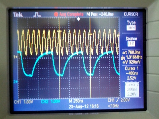
We are using MSP430F2012 USI I2C to driver an I2C slave EEPROM. The I2C clock is configured to use SMCLK with a divisor of 2 (divide by 4).  SMCLK is configured to be  the same as the MCLK from DCO at 8MHz. We expected that the I2C master clock to be 2MHz, but what it really came out of the USI, measured only 1.3MHz, while the SMCLK being 8MHz correctly, see attached the scope shot (the yellow line is SMCLK and the blue line is the I2C clock). If we configure the divisor to 4, instead of getting an I2C clock of 1MHz, we only got about 750Khz, very strange. Can anyone please explain what's happening here? Thanks a lot.

Cheers,

Rong

  • I2C uses a mechanism called 'clock stretching'. Since no I2C peer actively pulls SCL high, teh I2C master will release SCL (so it cqn go high) and then stops clock generation until it is actually gone high (and not held low by other peers, or, in your case, by line capacitance).

    In your scopeshot, when SCL begins to rise, this is when the master has released SCL. But SCL raises slowly, so the time until it reaches 'high' state is added to the cycle time. adding another one or two SMCLK cycles to the "high" phase.

    Well, your waveform doesn't look good anyway. SCL is rising much too slow, yso your pullups are not strong enough for this baudrate. But the fall time is also very high. Which indicates that your capacitive load on teh line is way too much.

    Anyway, the MSP I2C is not specified for such an I2C baudrate. The 5438 datasheet lists 400kHz (fast I2C) as maximum I2C clock frequency. 2MHz is a little bit too much.

  • Thanks. You are quite right. Almost forgot it's a multi-master chip, and thought the SCL was push-pull. For some reason, we do have a slow rising time and falling, we did have a 450R pull-up on both SCL and SDA but for some reason, it didn't help much.

    A slight off-topic question, do you know if the spy-bi wire works on MSP430F2012 at all? We spent a lot of time on it but couldn't get it to work. We had MSP430F2002 on the same PCB, it only worked with a very short ribbon cable (<2cm) between the board and the programmer, anything longer just wouldn't work. JTAG worked on the same board without any issue.

  • Rong Shen said:
    Almost forgot it's a multi-master chip, and thought the SCL was push-pull.

    Has nothing to do with teh chip supporting multi-master. I2C bus itself is defined this way. It not only allows for multi-master but also gives the ability of signalling 'busy' state to the master without additional lines or status bytes.

    450R pullup is very strong and explains the long fall time. 4,7k to 10k are typical values. However, this doesn't explain the slow rise time then. nevertheless, MSP I2C is limited to 400kHz, so with 1/5 of the current clock speed, things will look much nicer.

    Rong Shen said:
    do you know if the spy-bi wire works on MSP430F2012 at all

    Yes, the 2012 supports SBW. But if you use SBW, you'll have to limit any startup capacitor on RST to 2.2nF or separate it (and the pullup) with an additional 1k resistor from the RST pin and the SBW signal. Else it will work as low-pass filter to the SBW signal.

  • Thanks for the reply on SBW, we tried all combinations, 2.2nf cap, no cap, pullups etc etc. Nothing seemed to work. Even when it worked with f2002, it was very flakey, and only worked with 10mm cable, could not operate with external psu, could not stepping through the code, and reset debugger if a finger was close. Any ideas?

  • usually, people don't have probelms with SBW. So maybe you're doing something wrong.

    It might be supply voltage. When usign the LaunchPad or any EXP-EZ for programming, the target board supply voltage must be the same as teh programmer voltage (usually 3.3V). Also, don't forget the GND connection! (sounds dumb, but happened several times).
    For the UIF programmer, you'll hjave to either supply the target from the UIF or connect the targets supply voltage to the voltage sense pin of the UIF, so it can adjust its signal levels accordingly.

**Attention** This is a public forum