


Other Parts Discussed in Thread: MSP430FG4618
Hello,
I am a novice at MSP430. Now I have some problems between MSP430FG4618/f2013 and RS232.
I have a program written by others in PC. The program(written in Visual Basic) is able to transmit data or receive data with RS232. So, I want to use a cable of RS232 to connect between PC and MSP430FG4618 to make a “echo system”. (Namely, I send out some data(ex. numbers, alphabets) by the program. The data should transmit from PC to MSP430FG4618, and echo what PC sends. For example, I send a character of “1” from the program, the data is sent to the board, and the board should also echo “1” to the program in PC.
I use MSP430FG461x Code Examples as following. I change the line P4SEL |= 0x0C0; to P2SEL |=0x030;, because I find using P4 can’t work. Strangely, When I use P2(the same effect of P4), it works.
//******************************************************************************
// MSP430xG46x Demo - USCI_A0, Ultra-Low Pwr UART 9600 Echo ISR, 32kHz ACLK
//
// Description: Echo a received character, RX ISR used. Normal mode is LPM3,
// USCI_A0 RX interrupt triggers TX Echo.
// ACLK = BRCLK = LFXT1 = 32768, MCLK = SMCLK = DCO~1048k
// Baud rate divider with 32768hz XTAL @9600 = 32768Hz/9600 = 3.41 (0003h 03h )
// //* An external watch crystal is required on XIN XOUT for ACLK *//
//
//
// MSP430xG461x
// -----------------
// /|\| XIN|-
// | | | 32kHz
// --|RST XOUT|-
// | |
// | P4.7/UCA0RXD|------------>
// | | 9600 - 8N1
// | P4.6/UCA0TXD|<------------
//
// K. Quiring/ M. Mitchell
// Texas Instruments Inc.
// October 2006
// Built with CCE Version: 3.2.0 and IAR Embedded Workbench Version: 3.41A
//******************************************************************************
#include "msp430xG46x.h"
void main(void)
{
volatile unsigned int i;
WDTCTL = WDTPW+WDTHOLD; // Stop WDT
FLL_CTL0 |= XCAP14PF; // Configure load caps
do
{
IFG1 &= ~OFIFG; // Clear OSCFault flag
for (i = 0x47FF; i > 0; i--); // Time for flag to set
}
while ((IFG1 & OFIFG)); // OSCFault flag still set?
P2SEL |=0x030;
//P4SEL |= 0x0C0; // P4.7,6 = USCI_A0 RXD/TXD
UCA0CTL1 |= UCSSEL_1; // CLK = ACLK
UCA0BR0 = 0x03; // 32k/9600 - 3.41
UCA0BR1 = 0x00; //
UCA0MCTL = 0x06; // Modulation
UCA0CTL1 &= ~UCSWRST; // **Initialize USCI state machine**
IE2 |= UCA0RXIE; // Enable USCI_A0 RX interrupt
_BIS_SR(LPM0_bits + GIE); // Enter LPM0, interrupts enabled
}
// Echo back RXed character, confirm TX buffer is ready first
#pragma vector=USCIAB0RX_VECTOR
__interrupt void USCIA0RX_ISR (void)
{
while(!(IFG2&UCA0TXIFG));
UCA0TXBUF = UCA0RXBUF; // TX -> RXed character
}
I measure the UCA0RXD and UCA0TXD of H4 in MSP430FG4618 Pin Access.
If I enter “2” in the program in my PC, UCA0RXD will appear as following
(Because my program would add line feed(\n) and carriage return (\r) automatically, the data bits appears in the left and the right is the bits of line feed and carriage return.)

But if I measure the pin of UCA0TXD, I find the echo data will change to the following picture. (It can't return the same data as original one)
In the left, the data bits still remain. However, in the right, the bits of line feed and carriage return lose. Instead, it appears inappropriate signal. Therefore, it makes the echo signal is not exact.

I test many different characters to enter. They all have the disappearance of the bits of line feed and carriage return. However, the bits of data still remain.
But sometimes, the result is unknown. For example, if I enter the character of “1”
I measure the pin of UCA0RXD, the result is exact.
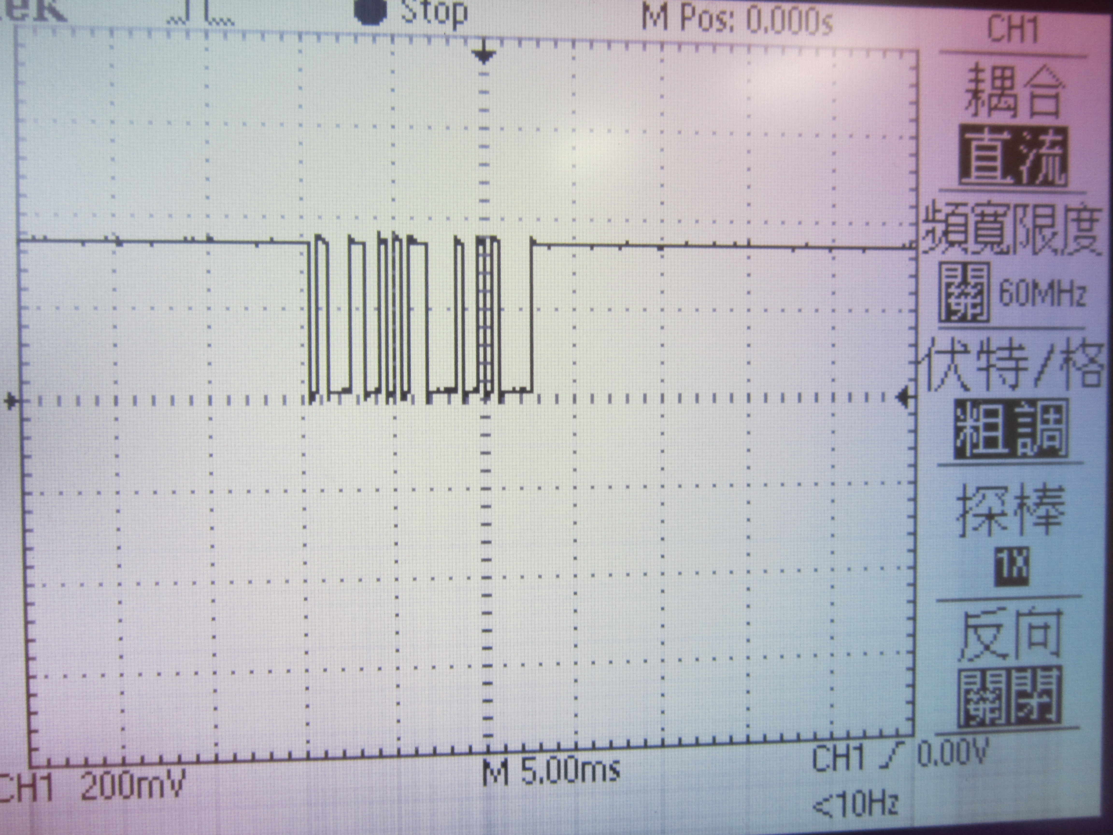
But if I measure the pin of UCA0TXD, the bits of data all disappear.
And the line feed and carriage return also disappear, still remaining the strange signal.

I really feel confused about the situation. I have no idea to solve the strange problem.
