This thread has been locked.

If you have a related question, please click the "Ask a related question" button in the top right corner. The newly created question will be automatically linked to this question.

Delay when starting timer in MSP430FR5739

Other Parts Discussed in Thread: MSP430FR5739

Hi,

When working with timers in the MSP430FR5739 I can detect a certain delay (not constant and always in the range of µs) when switching on the signal and outputing the capture/compare unit output. I will expect having a delay of some nanoseconds but µs are a good bunch of cycles in between.

Does anyone know where does this delay come from? Is it possible to avoid it?

As an example for reproducibility I am using the next code:


#include  <msp430fr5739.h>

;------------------------------------------------------------------------------

            ORG     00FC00h                  ; Program Start

;------------------------------------------------------------------------------

RESET       mov.w   #01FFFh,SP        ; Initialize stackpointer

StopWDT     mov.w   #WDTPW+WDTHOLD,&WDTCTL  ; Stop WDT

            mov.w   #CSKEY, &CSCTL0

            mov.w   #DCOFSEL0+DCOFSEL1+DCORSEL, &CSCTL1    //DCO runing at 24MHz

            mov.w   #SELM__DCOCLK+SELA__DCOCLK+SELS__DCOCLK, &CSCTL2  //clocks running at 24MHz

            mov.w #00h,&CSCTL3

            bis.w  #DIVA__2,&CSCTL3  //divide the auxiliary clock frequency by 2


            bis.b #BIT0+BIT1, &P1DIR     //output the timer signal in P1.1                 

            bis.b #BIT0 + BIT1, &P1OUT                        

            bis.b #BIT1,&P1SEL0 //secondary function selected in port direction


        //timer setup for generating a 600KHz clock signal


        bis.w  #TAIDEX_4,&TA0EX0  //divide the frequency by 5, the auxiliary clock was already divided by 2 so we get f/10=1200KHz

        mov.w  #1,&TA0CCR0       

        mov.w  #OUTMOD_4, &TA0CCTL2 //PWM output mode: 4 - toggle */            

        mov.w  #1,&TA0CCR2

      bis.w  #TASSEL__ACLK+MC_3+TACLR,&TA0CTL // Timer A0 mode control: 3 - Up/Down */and Timer A source ACLK


FF:           jmp FF

                nop

;-------------------------------------------------------------------------------

            COMMON  INTVEC                  ; Interrupt Vectors

;-------------------------------------------------------------------------------

            ORG     RESET_VECTOR            ; POR, ext. Reset

            DW      RESET

             END

I attach the result that I get in the Osci when meassuring the output on the pin P1.1:
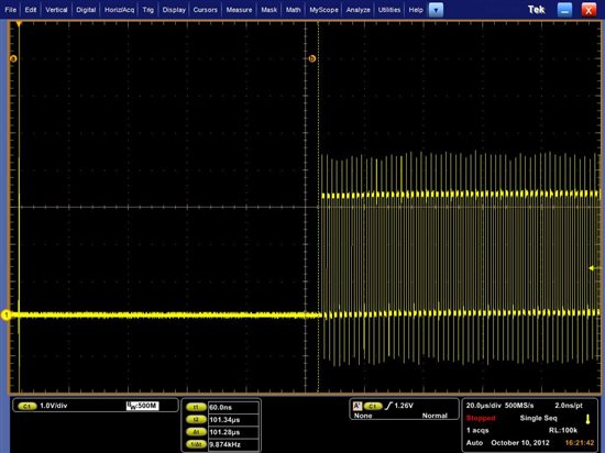

 As shown in the Osci the delay between the port is switched to timer output mode (bis.b #BIT1,&P1SEL0 ) till we get the timer output is around 100µs. If we are working at

24MHz, these are 2400 cycles in between.


I would appreciate any help.


Thanks in advance.

  • Any TI engineer watching this?

    I looked into this and found indeed the TimerA0 will not start counting right away if ACLK is used -- where ACLK is setup to be identical to SMCLK. When ACLK is used, TA0R stays =0000 for tens to hundreds clocks and then start to count. When the identical SMCLK is used instead, TA0R starts to count right away as expected.

    #include  <msp430fr5739.h>
    ;------------------------------------------------------------------------------
                RSEG   CODE
    ;------------------------------------------------------------------------------
    main:       mov.w  #WDTPW+WDTHOLD, &WDTCTL

    ; set up MCLK = DCOCLK/1; ACLK = DCOCLK/8; SMCLK = DCOCLK/8
                mov.w  #CSKEY, &CSCTL0
                mov.w  #SELM__DCOCLK+SELA__DCOCLK+SELS__DCOCLK, &CSCTL2
                mov.w  #DIVM__1+DIVA__8+DIVS__8, &CSCTL3

    ; clear & start TimerA0 to count ACLK in continuous mode
    ; (alternatively, count SMCLK instead)
    ; *** ***   mov.w  #TASSEL__SMCLK+MC__CONTINOUS+TACLR, &TA0CTL
                mov.w  #TASSEL__ACLK+MC__CONTINOUS+TACLR, &TA0CTL

    ; store consecutive TimerA0 counts in RAM until RAM is full
                mov.w  #-0400h, R4
    store:      mov.w  &TA0R, 2000h(R4)
                add.w  #2, R4
                jnz    store
    brkpnt:     jmp    brkpnt    ; *** *** set breakpoint here *** ***
                nop

    ; *** *** view contents of RAM to see how TimerA0 behaves *** ***
    ;
    ; you will see that it stay 0 for a long time before it increments
    ; this is unexpected
    ;
    ; had you use the alternative TimerA0 setting to count SMCLK then
    ; you will see it starts counting right away (as expected)
    ;
    ; note that ACLK and SMCLK both are set up as DCOCLK/8
    ; however, TimerA0 behaves differently

    ;------------------------------------------------------------------------------
                RSEG   RESET
                DW     main
    ;------------------------------------------------------------------------------
                END


  • Hi OCY and Aitor,

    The CS module synchronizes the switching of a clock's sources.  As a test, can you add a delay after writing to CSCTL2, like this:

    ; set up MCLK = DCOCLK/1; ACLK = DCOCLK/8; SMCLK = DCOCLK/8
                mov.w  #CSKEY, &CSCTL0
                mov.w  #SELM__DCOCLK+SELA__DCOCLK+SELS__DCOCLK, &CSCTL2
                mov.w  #DIVM__1+DIVA__8+DIVS__8, &CSCTL3

                mov.w  #0, R4 ; The CS module synchronizes all clock
    wait:       sub.w  #1, R4 ; switchovers.  Wait here for the next
                jne    wait   ; rising edge on the previous ACLK source.

    ; clear & start TimerA0 to count ACLK in continuous mode
    ; (alternatively, count SMCLK instead)

    ; *** ***   mov.w  #TASSEL__SMCLK+MC__CONTINOUS+TACLR, &TA0CTL
                mov.w  #TASSEL__ACLK+MC__CONTINOUS+TACLR, &TA0CTL

    It's in section 3.2.8 of the old FRxx manual I have.

    Jeff

  • Here's an "elegant" solution for changing the ACLK source from XT1 to the DCO.  The trick is a very short-term usage of XT1 for MCLK.


    RESET       mov.w   #01FFFh,SP        ; Initialize stackpointer

    StopWDT     mov.w   #WDTPW+WDTHOLD,&WDTCTL  ; Stop WDT

                mov.w   #CSKEY, &CSCTL0

                mov.w   #DCOFSEL0+DCOFSEL1+DCORSEL, &CSCTL1    //DCO runing at 24MHz

                mov.w   #SELM__XT1CLK+SELA__DCOCLK+SELS__DCOCLK, &CSCTL2  // force MCLK to wait for ACLK switchover

                mov.w   #SELM__DCOCLK+SELA__DCOCLK+SELS__DCOCLK, &CSCTL2  // clocks running at 24MHz

    It's a low-power solution too.

    Jeff

  • Jeff,

    You are right. I did not know that. After I inserted the delay you suggested (the label wait: was miss placed, but I know what you mean), it is much better now.

    When using SMCLK, TA0R counts: 0, 1, 2, 3, ... When using ACLK, TA0R counts: 0, 0, 1, 2, 3, ...

    I will investigate more details when I have time to do it.

    Thank you,

    -- OCY

  • Thanks OCY! 

    I have now moved the wait: label in my original post, just for posterity.

    Jeff

  • Thank you very much Jeff and OCY!

    The information was really helpful. I will switch to SMCLK as you suggested.

    Regarding the TI engineers, I already contacted them and they told me that they will investigate on that.


    Thanks again!

    Aitor

  • Hi Aitor,

    OCY and I probably weren't as clear as we could have been.

    There is no bug here.  The delay you are observing is the result of the MCU operating as designed.

    After reset, ACLK is sourced from XT1.  (Actually, because XT1 is not oscillating after reset, VLO stands in for XT1, but that's not critical to this discussion.)  When you write to CSCTL2 to change ACLK from XT1 to DCO, the clock module takes quite a long time to make that switchover.  Meanwhile you keep executing instructions while ACLK is stalled.  In your oscilloscope pictures, it's this switchover delay that you are observing.  See section 3.2.8 of the FRxx manual for an explanation of the switchover (and why it takes so long in this case).

    After reset, SMCLK is sourced from the DCO.  In your configuration, you don't switch SMCLK to another source, so there is no switchover delay.

    Jeff

  • Hi Jeff,

    Thanks again for the clear explanation. 

    Anyway I contacted the Engineers form TI before reading all your answers so they where also looking into my issue.

    Aitor


  • Jeff Tenney said:
    mov.w   #SELM__XT1CLK+SELA__DCOCLK+SELS__DCOCLK, &CSCTL2  // force MCLK to wait for ACLK switchover
    mov.w   #SELM__DCOCLK+SELA__DCOCLK+SELS__DCOCLK, &CSCTL2  // clocks running at 24MHz


    Unfortunately, this waits for several XT1CLK cycles. So the delay is rather large.
    It can be reduced a bit when loading SELM__DCOCLK+SELA__DCOCLK+SELS__DCOCLK into a register before switching to MCLK to XT1. Unfortunately, indirect register addressing mode is not available for destination, so the switch back to DCOCLK takes at least three XT1 clock cycles. (4 when using an immediate value, as in the original code).

    Edit: I'd propose simply waiting for TAR to increment the first time. Then reset it to start the real counting, if required. This reduces the delay to less than one XT1 clock cycle (depending on how much of the current cacle has already passed when the wait begins)

**Attention** This is a public forum