Other Parts Discussed in Thread: MSP430F6638, CODECOMPOSER, MSP430F6630
Hi Everyone,
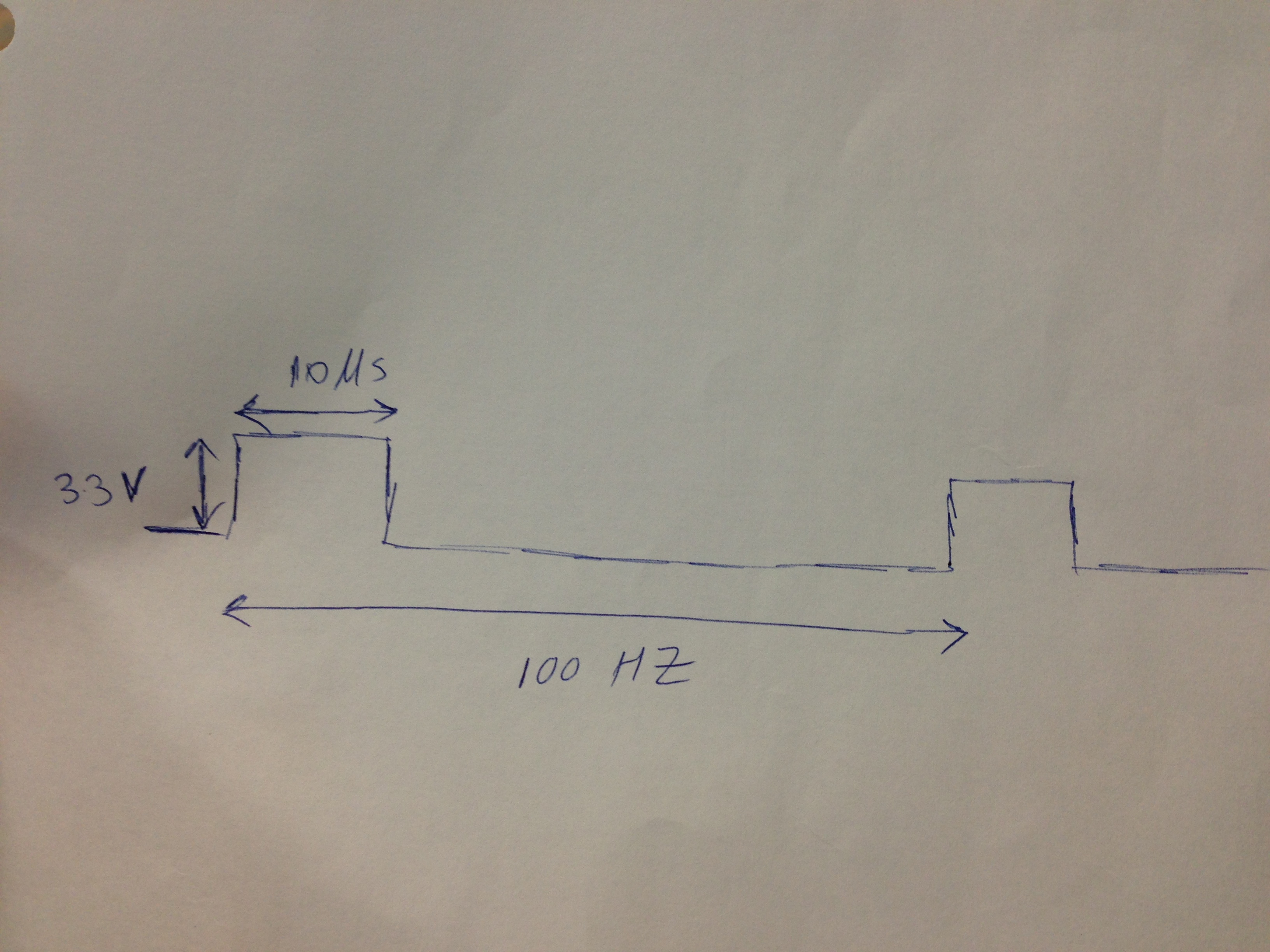
I need to write a simple function generator for my MSP430F6638 MCU. Does anyone have any sample code?
Thanks,
Arash
Other Parts Discussed in Thread: MSP430F6638, CODECOMPOSER, MSP430F6630
Hi Everyone,
I need to write a simple function generator for my MSP430F6638 MCU. Does anyone have any sample code?
Thanks,
Arash
**Attention** This is a public forum