This thread has been locked.

If you have a related question, please click the "Ask a related question" button in the top right corner. The newly created question will be automatically linked to this question.

Unknown Device error when programming CC430F5137

Other Parts Discussed in Thread: CC430F5137

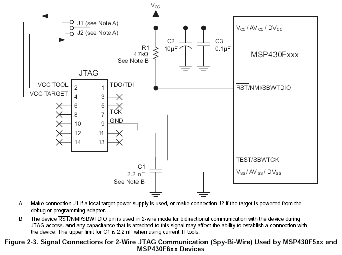
I am trying to program a board I built that's got a CC430F5137 on it by using Spy-by-wire. I'm using CCS 5.2 and programming with an MSP-FET430UIF. I was able to correctly program a CC430F5137 on a TI dev board that I had, but when I try to program my own board, I get the "Unknown Device" error. Everything I've read suggests that the problem is a JTAG wiring issue. I'm using the target voltage option (so the FET430 senses and matches it's own voltage to the board voltage). I'm using this schematic:

Here's the part of my schematic that has the JTAG interface:

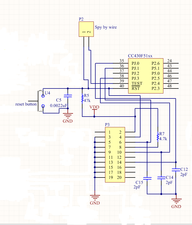
Note that my schematic only shows part of the CC430. I'm have pin 2 on P3 connected to pin 4 of the programmer, pin 3 of P3 connected to pin 9 of the programmer, pin 1 of P2 is connected to pin 1 of the programmer, and pin 2 of P2 is connected to pin 7 of the programmer. I tried removing C5, but it didn't help. I know that capacitance on that line needs to be under 2.2nF. Nothing else is connected to P3, so you can ignore those other connections. Any idea on what could be causing CCS to not detect my chip?

  • Hello Hunter (or Scott?),

    I have to say you have an awesome name.  Both names are well known first names and last names too!  (I'm guessing you've heard that before.)

    Back on topic, did you tell CCS that you are using SBW?  Or is there an "automatic" setting?  (I use IAR.)  In any case, select SBW if you haven't already.  The dev kit you were using almost certainly uses 4W JTAG.

    I don't see anything wrong with your redacted schematic.  You didn't happen redact a supply-voltage supervisor with push-pull reset driver did you?  Or does anything of consequence connect to pin 4 of P3? (I know you said nothing else on P3, just being thorough.)

    Cheers!

    Jeff

  • Hey Jeff,

    My first name is Hunter, but I'm glad you think it's awesome haha. As far as I'm aware, CCS automatically determines if it's in SBW or 4W mode. The MSP-FET430UIF programmer is in a plastic enclosure, so there's no jumpers that I can move to put it in a different mode (I even took the case off but there weren't any jumpers inside). If there is a way to change the mode in CCS, I'm not sure how to do it.

    The only thing that the schematic didn't show as far as power goes is a voltage regulator that feeds all of VDD, some decoupling caps, and a ferrite bead. Pin 4 on P3 is not connected to anything.

    Thanks for the help!

  • Hunter Scott1 said:
    The MSP-FET430UIF programmer is in a plastic enclosure, so there's no jumpers that I can move to put it in a different mode

    No, the mode is controlled by software.

    The Elprotronic software has a setting to explicitely schoose the mode when teh device supports both. Unless CCS tries both and only complains if both fail, there must be a setting too. There are different possible places. WHere you select the device, where you select the FET (AFAIK, CCS can deal with several FETS on a PC) or wher you set whether to emulator or simulator or whether to upload only or upload and debug.
    I don't use CCS, but there are so many places where something can hide - just like the office 'ribbons' on windows.

    For reference, please post when/where you found it

  • I made sure that my target FET was correct. I have TI MSP430 USB1 [default] selected, which gives me the unknown device error. If I pick any other options (like TI MSP430 USB2 or TI MSP430 USB3) then I get an error that "No USB FET was found". I searched through the CCS 5.2 user manual for anything on SBW, but couldn't find anything. 

    Jens-Michael Gross said:
    The Elprotronic software has a setting to explicitely schoose the mode when teh device supports both. Unless CCS tries both and only complains if both fail, there must be a setting too. 

    According to this post, CCS automatically chooses SBW or 4W for you: http://e2e.ti.com/support/development_tools/code_composer_studio/f/81/p/206780/733172.aspx#733172

  • SBW mode can be picky about wire lengths so make sure your connections to the programmer are as short as possible.

  • I have some wires going from my board to the ribbon cable that came with the programmer, and I shortened them to be about an inch long, but I'm still getting that unknown device error. I'm really stumped on what the problem could be.

  • I removed the 2.2nF cap (it's an open circuit now) since apparently that line is sensitive to capacitance. Should I try adding it back in or adding in a smaller value maybe?

  • I don't think that tiny capacitance is the problem.  (Especially since you removed the cap and still can't get proper communication.)

    My guesses:

    • pin number confusion (male/female/wire-side view/pin-side view/etc)
    • CCS project is stuck on 4W JTAG because the dev kit used 4W JTAG.

    Good luck!

    Jeff

**Attention** This is a public forum